
 WhatsApp: +86 16626708626
 Email:
  Phone: +86 16626708626
Description
Key Technical Specifications
| Parameter | Reported Specification |
|---|---|
| Manufacturer | Yokogawa |
| Model | 2302-32-VLE-2 |
| Product Category | Industrial data acquisition / I/O hardware |
| Input Channels | 32 voltage channels* |
| Input Resolution | 16 bit* |
| Input Range | ±10 V* |
| Output Channels | 2 voltage channels* |
| Output Resolution | 16 bit* |
| Output Range | ±10 V* |
| Mounting | DIN rail* |
| Application | Data acquisition, control, machine/process monitoring |
| Communication Interface | Not verified |
| Host System | Not verified |
| Firmware | Not verified |
| Certifications | Some suppliers report UL, CSA, and CE; OEM verification required |
*These specifications appear in current third-party catalog records and should not be treated as OEM-verified until the nameplate or Yokogawa documentation confirms them.
Product Introduction
The Yokogawa 2302-32-VLE-2 is identified by multiple industrial automation suppliers as a data-acquisition component associated with Yokogawa systems. Several listings describe a 32-channel voltage-input configuration with 16-bit resolution and ±10 V input capability.
There is an important identification issue with this part number. Other listings describe the same number as an electronic hybrid recorder or electrical measurement instrument, with specifications that do not match the 32-channel I/O description. For procurement and replacement work, the physical nameplate, original system BOM, and OEM documentation should take precedence over reseller descriptions.
Installation & Configuration Guide
Stage 1: Pre-Installation Preparation — 10–20 Minutes
⚠️ Safety First: Put the associated control or measurement system into its approved maintenance state. Follow plant LOTO procedures before disconnecting powered I/O.
Tools Required:
- ESD wrist strap
- Digital multimeter
- Appropriate screwdriver
- Wire labels
- Smartphone/camera
- Approved Yokogawa system documentation
Data Backup:
- Record the complete 2302-32-VLE-2 nameplate information.
- Photograph the front, side, and terminal markings.
- Photograph every field connection.
- Record channel assignments.
- Record input ranges and scaling.
- Record output assignments if the installed unit has analog outputs.
- Document the host controller or acquisition system.
- Record any module address, communication, or configuration parameters.
- Compare the physical unit against the original system BOM.
⚠️ Critical: Because publicly available specifications for this exact model conflict, do not configure a replacement from a generic online listing. Confirm the hardware against the actual installed unit first.
Stage 2: Removing the Old Module — 5–10 Minutes
- Place the system in its approved maintenance state.
- Isolate the relevant power source.
- Verify the circuit is de-energized.
- Label every field conductor.
- Photograph the complete terminal arrangement.
- Record the channel-to-signal mapping.
- Disconnect field wiring without pulling on conductors.
- Disconnect the communication or backplane connection, if applicable.
- Release the module from its mounting hardware.
- Remove it carefully without damaging adjacent modules or wiring.
- Inspect the terminal block and mating connectors.
Stage 3: Installing the New Module — 10–15 Minutes
- Verify the replacement marking is 2302-32-VLE-2.
- Compare physical dimensions and connector arrangement with the original.
- Verify the exact I/O configuration before connecting power.
- Install the module in the original mounting position.
- Reconnect field wiring according to the approved drawing.
- Verify every channel against the photographs.
- Confirm analog signal polarity.
- Check shield and signal-ground arrangements.
- Verify any output wiring separately.
- Secure all terminals.
Self-Checklist:
- Exact model verified
- Physical connector arrangement matches
- Channel map documented
- Input polarity checked
- Output wiring checked
- Shielding verified
- Mounting secured
- Configuration backed up
Stage 4: Power-On & Testing — 20–40 Minutes
- Perform a complete wiring inspection.
- Measure the supply voltage before energizing.
- Power the module according to the manufacturer’s system procedure.
- Check status indicators.
- Confirm the host system recognizes the hardware.
- Verify each configured input channel.
- Inject known voltage signals where the system design permits.
- Compare measured values with the engineering scaling.
- Test any analog output channels separately.
- Verify the controller or data-acquisition software receives the expected values.
- Check diagnostics for channel or communication faults.
- Restore the system to normal operation only after the I/O checks pass.
Common Replacement Pitfalls
❗ 1. Trusting a Marketplace Specification Without Verification
The available listings disagree about what 2302-32-VLE-2 actually is. One source lists 32 voltage inputs and 2 voltage outputs; another describes it as a hybrid recorder. That is too large a discrepancy to ignore during a replacement.
❗ 2. Assuming ±10 V Is Confirmed
The ±10 V input specification appears in multiple reseller listings, but I did not locate an OEM Yokogawa datasheet confirming it for this exact part number. Treat it as a reported specification until verified against the hardware documentation.
❗ 3. Ignoring Channel Scaling
Even when the replacement hardware is electrically correct, incorrect engineering-unit scaling can produce incorrect process values. Record the original channel configuration before removing the module.
❗ 4. Mixing Up Data-Acquisition and Recorder Hardware
Several third-party pages appear to reuse generic descriptions for this part number. Do not assume the module belongs to a particular Yokogawa platform based solely on a reseller category.
❗ 5. Buying Without an Actual-Unit Photograph
For this particular model, I would request a clear photograph of the nameplate and connector/terminal side before approving a replacement. That is more reliable than accepting an unverified catalog description.
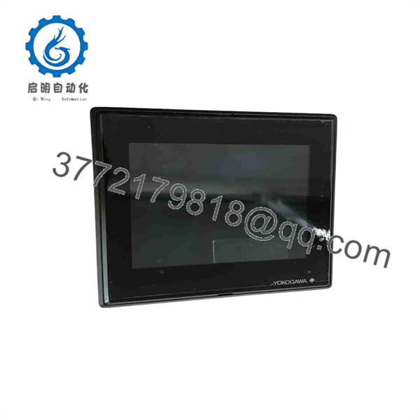
2302-32-VLE-2
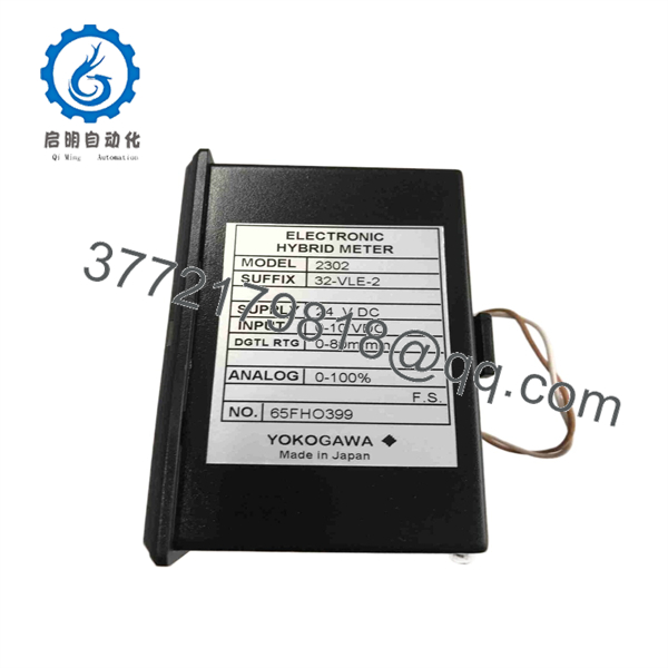
2302-32-VLE-2
Frequently Asked Questions (FAQ)
1. What is the Yokogawa 2302-32-VLE-2?
Multiple industrial automation suppliers identify it as a Yokogawa industrial data-acquisition/I/O component. Several current listings describe 32 voltage inputs and 2 voltage outputs. However, the exact OEM function has not been independently confirmed from a Yokogawa datasheet located in this search.
2. Does the 2302-32- have 32 voltage inputs?
That is the most consistently reported technical description found in current supplier records. Those listings specify 32 voltage inputs, 16-bit resolution, and ±10 V input range. Because no OEM datasheet was located to confirm these values, verify them against the physical unit before system design or replacement approval.
3. Does it have analog outputs?
Some supplier specifications report two voltage-output channels with 16-bit resolution and ±10 V output range. This information is not independently verified against an OEM Yokogawa document in the available sources.
4. Is the 2302-32- a Yokogawa DCS module?
Third-party industrial automation databases consistently associate the part number with Yokogawa, but the exact host-system family has not been established from authoritative documentation. One supplier describes it generically as a Yokogawa DCS data-acquisition component.
5. Is the 2302-32- obsolete?
The available sources do not establish an authoritative OEM lifecycle status for this exact part number. Given the limited documentation and inconsistent catalog descriptions, treat it as legacy/uncertain-status hardware until Yokogawa or the original system documentation confirms its lifecycle.
6. Can I use a generic 32-channel analog-input module as a replacement?
Not without an engineering compatibility review. You need to verify the electrical input range, resolution, isolation, connector pinout, power requirements, host interface, scan behavior, software configuration, and signal scaling. A module with the same channel count is not automatically compatible.
7. What should I verify before purchasing a 2302-32-?
Request and verify:
- Exact nameplate and full part number
- Physical connector/terminal arrangement
- Original system or equipment model
- Input/output channel configuration
- Supply voltage
- Firmware or revision information
- Tested operating status
- Actual-unit photographs
- New Original, New Surplus, or Refurbished condition
For this model specifically, a photograph of the actual nameplate is highly valuable because the public specifications are inconsistent.



