
 WhatsApp: +86 16626708626
 Email:
  Phone: +86 16626708626
Description
Key Technical Specifications
| Parameter | Value |
|---|---|
| Manufacturer | Yokogawa Test & Measurement |
| Model | 720254 |
| Module Designation | 720254-4 |
| Product Type | High-Resolution Isolation Module |
| Number of Channels | 4 |
| Input Connector | BNC |
| Maximum Sampling Rate | 1 MS/s |
| A/D Resolution | 16 bit |
| Bandwidth | 300 kHz |
| DC Accuracy | ±0.25% |
| Maximum Measurement Voltage | 600 V DC + AC peak with specified probe |
| Direct Input Measurement Voltage | 200 V DC + AC peak |
| Isolation | Channel input isolation using Yokogawa IsoPRO technology |
| Compatible Mainframes | DL950, DL850E, DL850EV, DL350 |
| Typical Application | Power-generator monitoring, power-supply testing, dynamic waveform analysis |
Yokogawa specifies 1 MS/s sampling, 16-bit resolution, 300 kHz bandwidth, ±0.25% DC accuracy, and four isolated BNC input channels for the 720254. With compatible probes, the module supports measurements up to 600 V; direct input is rated to 200 V DC + AC peak.
The module is designed for Yokogawa ScopeCorder platforms and can be used for high-speed multi-channel measurements where electrical isolation is required. Yokogawa’s DL850E documentation confirms that up to eight input modules can be installed in a ScopeCorder, depending on the mainframe configuration.
Product Introduction
The Yokogawa 720254 is a four-channel, 16-bit isolated input module for ScopeCorder measurement systems. It samples at up to 1 MS/s per channel and provides 300 kHz bandwidth, making it suitable for waveform capture, power-generator testing, and dynamic measurements on multi-output power supplies.
The main reason to specify this module rather than a general-purpose voltage input card is its combination of high sampling rate, four-channel isolation, and 600 V measurement capability when used with the specified Yokogawa probes. It is compatible with DL950, DL850E, DL850EV, and DL350 platforms.
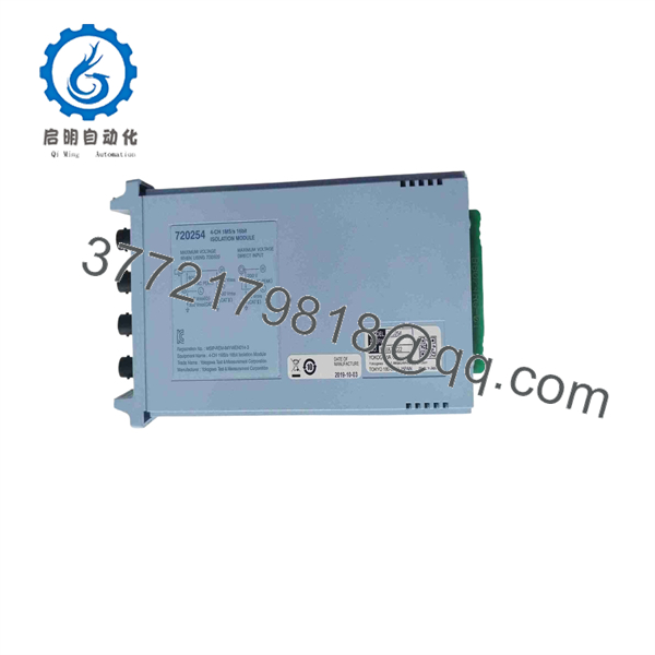
720254
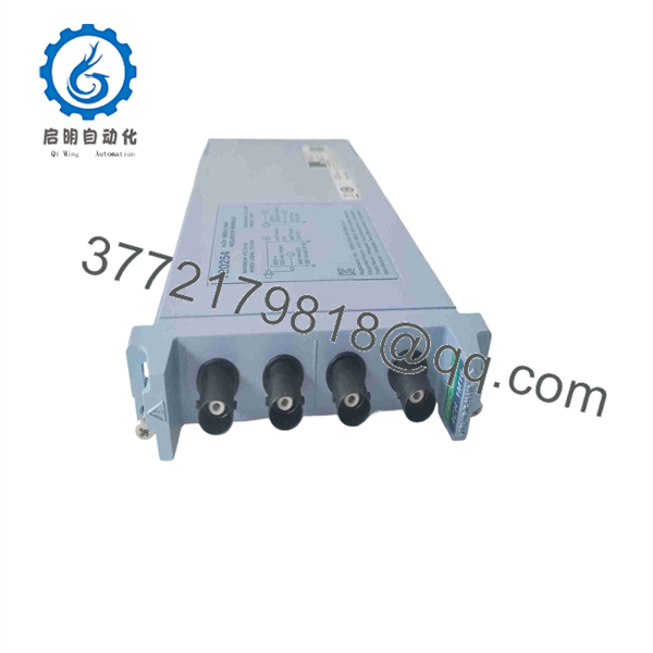
720254
Installation & Configuration Guide
Stage 1: Pre-Installation Preparation — Approx. 5 Minutes
⚠️ Safety First
- Stop the measurement system and isolate the equipment under test as required by the site’s electrical safety procedure.
- Confirm the measured circuit is within the 720254 voltage limits.
- Never connect a voltage source exceeding the module’s specified input rating.
- Verify whether the measurement will use direct BNC input or a compatible Yokogawa probe.
- Confirm the ScopeCorder mainframe model before installation.
Tools Required
- ESD wrist strap
- Appropriate screwdriver if required by the mainframe
- Multimeter
- BNC cables
- Compatible Yokogawa voltage probe where required
- Smartphone or camera for documenting the original installation
Configuration Check
Before removing an existing module:
- Record the ScopeCorder model.
- Record the existing module position.
- Photograph the front-panel labeling.
- Record probe type and attenuation.
- Save the measurement configuration if the application requires repeatability.
- Record channel scaling and bandwidth settings.
Yokogawa’s DL850E manual identifies the 720254 as a 4-channel 1 MS/s, 16-bit module, with each channel providing configurable measurement settings such as probe attenuation, bandwidth limit, coupling, and scaling.
Stage 2: Removing the Existing Module — Approx. 3–5 Minutes
- Stop acquisition before removing the module.
- Disconnect BNC cables from the module.
- Label each measurement channel.
- Release the module’s retaining mechanism.
- Pull the module straight out of the ScopeCorder slot.
- Inspect the connector and slot for contamination or mechanical damage.
- Keep the old module available until the replacement has passed testing.
⚠️ Do not force the module sideways. The rear connector must align correctly with the ScopeCorder backplane.
Stage 3: Installing the 720254 — Approx. 3–5 Minutes
- Verify the replacement marking: 720254.
- Confirm that the module matches the required ScopeCorder platform.
- Put on the ESD wrist strap.
- Align the module with the correct slot.
- Insert it straight into the mainframe.
- Secure the retaining mechanism.
- Reconnect the BNC cables according to the recorded channel assignments.
- Reconnect the correct voltage probes where applicable.
- Confirm the probe attenuation setting in the ScopeCorder software.
Self-Checklist
- Model marked 720254
- Correct ScopeCorder mainframe
- Module fully seated
- BNC connections secure
- Probe type verified
- Probe attenuation correct
- Channel assignments preserved
- Measurement voltage within specification
Stage 4: Power-On & Testing — Approx. 10 Minutes
- Power on the ScopeCorder mainframe.
- Confirm that the instrument recognizes the 720254.
- Check that all four channels are available.
- Configure the correct probe attenuation.
- Select the required input coupling and bandwidth.
- Apply a known low-level test signal first.
- Confirm waveform amplitude and frequency.
- Increase the test signal only within the specified measurement range.
- Check all four channels for consistent operation.
- Save the verified measurement configuration.
⚠️ Do not use the 600 V rating as a blanket permission for direct connection. Yokogawa specifies 600 V measurement when used with the appropriate 700929, 702902, or 701947 probes, while direct input is specified at 200 V DC + AC peak.
Frequently Asked Questions (FAQ)
Q1. What is Yokogawa 720254?
The 720254 is a four-channel high-resolution isolated input module for Yokogawa ScopeCorder systems. It provides 1 MS/s sampling, 16-bit resolution, and 300 kHz bandwidth. Yokogawa’s current product information describes it as the 720254-4 four-channel module.
Q2. Which Yokogawa instruments are compatible with 720254?
Yokogawa lists the module for the DL950, DL850E, DL850EV, and DL350 ScopeCorder platforms. Always check the mainframe’s supported module list before installation, particularly with older hardware revisions.
Q3. What is the maximum voltage I can measure?
The published specification is 600 V DC + AC peak when used with specified Yokogawa probes. For direct input, the specified maximum is 200 V DC + AC peak. The distinction is important; do not interpret the 600 V figure as a direct BNC input rating.
Q4. Does 720254 have four isolated channels?
Yes. Yokogawa specifies four isolated input channels, each using a BNC input. The module uses Yokogawa’s IsoPRO isolation technology for isolated measurements.
Q5. Is 720254 the same as 720254-4?
Yokogawa’s current website uses 720254 as the ordering/model number and describes the product as 720254-4. The official ordering database also identifies 720254 as the four-channel high-speed isolated module. For procurement, use the complete marking shown on the physical module and the mainframe’s compatibility documentation.
Q6. What is the bandwidth and sampling rate?
The module provides 300 kHz bandwidth and a maximum 1 MS/s sampling rate, with 16-bit A/D resolution. These specifications make it suitable for dynamic voltage waveform measurements rather than only slow process-variable monitoring.
Q7. What condition should I specify when purchasing a replacement?
Specify the condition explicitly: Factory Sealed, New Original/New Surplus, or Refurbished (tested). For a measurement module, also ask whether the unit has a current calibration certificate or calibration data. Yokogawa notes that a Certificate of Conformance confirms compliance with published specifications but does not necessarily provide calibration measurement data.



