
 WhatsApp: +86 16626708626
 Email:
  Phone: +86 16626708626
Description
Key Technical Specifications
| Parameter | Specification |
|---|---|
| Manufacturer | Yokogawa Electric Corporation |
| Model | A1BA4D-05 |
| Product Type | Terminal Board for FIO |
| Board Family | A1BA4D |
| Signal Category | Analog I/O field wiring |
| Configuration | Single or dual-redundant analog I/O applications |
| Channel Configuration | 16-channel × 1 or 8-channel × 1 |
| Mounting | DIN rail |
| Protection Type | Basic type, no explosion protection |
| Associated System | Yokogawa FIO architecture |
| Approx. Net Weight | 0.3 kg |
| Shipping Weight | Approximately 1.5 kg |
The A1BA4D family is identified as an analog terminal-board assembly for FIO systems. Available documentation specifically lists the -05 version as the basic, non-explosion-protection variant.
A project cable schedule also shows A1BA4D-05 used as the terminal-board endpoint for Yokogawa AAI135-H50 and AAI835-H50 analog I/O modules through KS1 system cables. This provides useful evidence of its actual field installation role.
Important identification note: Some secondary listings incorrectly describe A1BA4D-05 as a controller, temperature transmitter, or analog input module. The stronger catalog evidence identifies it as a Yokogawa FIO analog terminal board, so it should not be purchased as a replacement for an AAI-series I/O module.
Product Introduction
The Yokogawa A1BA4D-05 is an analog terminal board used with Yokogawa Fieldbus I/O (FIO) installations. Its primary role is field wiring termination and signal interconnection between analog I/O system cabling and the plant-side instrumentation circuits. Catalog documentation identifies the family as a DIN-rail-mounted analog terminal-board assembly.
For maintenance teams, the key selection point is that -05 is a terminal-board component, not the analog I/O electronics themselves. Project documentation shows the board installed with Yokogawa AAI135-H50 and AAI835-H50 modules, making exact board type, system cable, and I/O-module compatibility important when replacing an existing assembly.
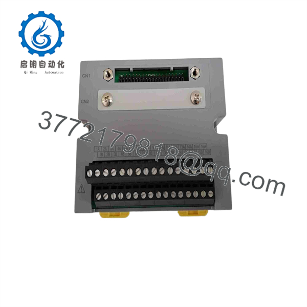
A1BA4D-05
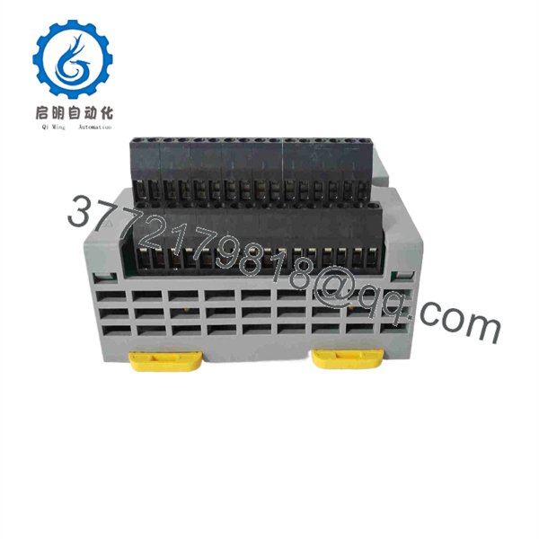
A1BA4D-05
Installation & Configuration Guide
Stage 1 — Pre-Installation Preparation
- Confirm the replacement marking is Yokogawa -05.
- Compare the existing terminal board, system cable, connector arrangement, and cabinet documentation.
- Apply plant LOTO procedures before accessing the cabinet.
- Allow the relevant system circuits to discharge for at least 5 minutes where applicable.
- Record terminal assignments and photograph the existing wiring before removal.
- Confirm whether the installation uses the board with AAI135-H50, AAI835-H50, or another supported FIO configuration.
Do not substitu simply because the mechanical appearance is similar. The terminal-board suffix defines the configuration and protection variant.
Stage 2 — Removing the Existing Board
- Verify the cabinet and loop identification.
- Label field wiring and system-cable connections.
- Disconnect wiring using the plant’s approved maintenance procedure.
- Release the terminal board from its DIN-rail or mounting arrangement.
- Inspect terminals, connectors, and cable ends for corrosion, loose hardware, or insulation damage.
- Retain the removed board until the replacement has passed commissioning checks.
Stage 3 — Insta
- Use appropriate ESD precautions when handling the board and associated connectors.
- Verify the replacement part number: .
- Mount the board in the same cabinet position and orientation as the removed unit.
- Reconnect the system cable and field wiring according to the original cabinet drawings.
- Verify every terminal against the wiring schedule before energizing the system.
- Check cable routing and shielding/grounding arrangements against the original installation.
itself should not be treated as a programmable controller. Configuration normally depends on the associated Yokogawa FIO hardware, system wiring, and control-system configuration rather than user firmware programming on the terminal board.
Stage 4 — Power-On & Testing
After installation:
- Check all terminal and connector connections.
- Verify there are no unintended shorts between signal circuits.
- Confirm the associated FIO module is correctly seated and identified.
- Restore power according to the site’s commissioning procedure.
- Check system diagnostics for channel or communication faults.
- Perform point-to-point verification against the I/O database.
- Validate representative analog signals before returning the loop to automatic control.
Common Replacement Mistakes
Wrong component type: is a terminal board, not an AAI analog I/O module.
Wrong suffix: Do not automatically substitute -06 or another variant. Product listings distinguish the -05 basic type from other suffix configurations.
Incorrect wiring: Photographing the original installation and comparing every terminal with the approved wiring diagram can prevent channel-to-channel errors during replacement.
Frequently Asked Questions (FAQ)
1. What is Yok?
is a Yokogawa analog terminal board for FIO systems. It provides the field-side termination/interface for analog I/O wiring rather than performing the signal-processing function of an AAI-series I/O module.
an analog input module?
No. It should be classified as a terminal board. The analog processing electronics are provided by the associated Yokogawa FIO I/O module. Project documentation, for example, connected with AAI135-H50 and AAI835-H50 modules.
3. What is the difference be and -06?
Both belong to the analog terminal-board family, but the suffix identifies the specific configuration. Available catalog data identifies as the basic type without explosion protection. Do not substitute another suffix without checking the Yokogawa system documentation.
4. require software programming?
The terminal board itself is not normally programmed like a PLC CPU or intelligent I/O module. The associated Yokogawa FIO hardware and control-system configuration determine signal processing, channel assignment, scaling, and control logic.
5 be used with any Yokogawa analog I/O module?
Not automatically. Compatibility should be confirmed against the exact FIO module, system cable, terminal assignment, cabinet design, and control-system architecture. A project record demonstrates its use with AAI135-H50 and AAI835-H50, but that should not be interpreted as universal compatibility.
obsolete?
Current aftermarket catalogs continue to list the part, but listing status and physical availability vary by supplier. For an operating plant, verify the actual part marking, revision, condition, and included accessories before purchase.
7. What should be verified before ordering?
At minimum, verify:
- Yok exact part number
- Existing terminal-board configuration
- Associated FIO I/O module
- System-cable type and connector arrangement
- Cabinet mounting arrangement
- New, surplus, refurbished, or used condition
- Required accessories and terminal hardware
- Seller traceability and inspection documentation
For a replacement project, the part number alone should not be the only compatibility check; the terminal-board configuration must match the existing FIO installation.



