
 WhatsApp: +86 16626708626
 Email:
  Phone: +86 16626708626
Description
Key Technical Specifications
| Parameter | Specification |
|---|---|
| Manufacturer | Yokogawa Electric Corporation |
| Part Number | AAI141 |
| System Compatibility | Field Control Units (FCU) for CENTUM VP & CENTUM CS 3000 |
| Input Signals | 16 Channels, 4 to 20 mA DC |
| Input Resistance | Power ON: 250 Ω, Power OFF: 500 kΩ or larger |
| Allowable Input Current | 24 mA DC |
| Accuracy | ±16 µA (±0.1% of full scale) |
| Data Update Cycle | 10 ms |
| Temperature Drift | ±16 µA / 10 °C |
| Power Consumption | Max 310 mA (5 V DC supply from Fieldnest Node Interface) |
| Weight | Approx. 0.3 kg (0.66 lbs) |
Product Introduction & Supply Chain Strategy
The Yokogawa AAI141 is a 16-channel analog input module designed for Yokogawa CENTUM VP and CENTUM CS 3000 DCS systems. It processes 4–20 mA DC signals from pressure, flow, temperature, and level transmitters. Engineered for high-density process environments, the AAI141 supports single or dual-redundant configurations in Field Control Units (FCU).
From a supply chain continuity perspective, keeping an AAI141 module in safety stock is essential. In continuous process industries (refineries, petrochemicals, power plants), an I/O card failure leads to unmonitored process loops, forcing loop manual control or unit trips. Refurbished modules frequently exhibit analog component drift, degraded filter capacitors, or worn backplane contacts that introduce loop noise. Sourcing New Surplus units guarantees factory measurement precision, original dielectric integrity, and zero-downtime protection against lead-time delays.
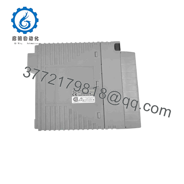
AAI141
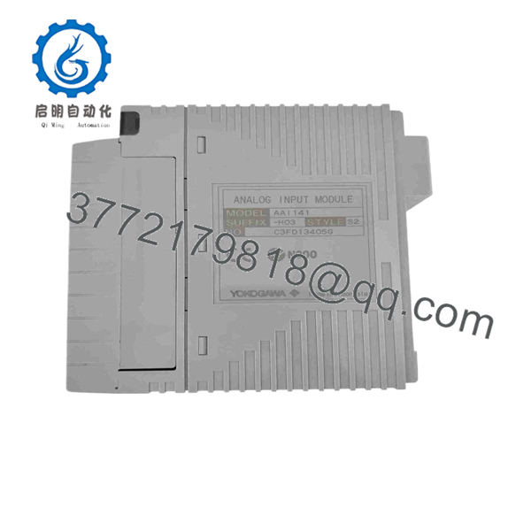
AAI141
Installation & Configuration Guide
1
Stage 1: Pre-Installation (Safety & Loop Prep)
Notify operators, switch loops to manual, and wear ESD strap
1.Stage 1: Pre-Installation (Safety & Loop Prep):Notify operators, switch loops to manual, and wear ESD strap.
Notify system operators that the target 16-channel I/O block will go offline. Put all associated control loops into Manual mode or set fallback safe values in the CENTUM software. Attach a grounded ESD wrist strap before touching the module. Record existing field terminal wiring or check the KS Cable / Pressure Clamp terminal block connection.
2
Stage 2: Module Extraction
Release module latch/screws and extract card from slot
2.Stage 2: Module Extraction:Release module latch/screws and extract card from slot.
Unscrew the top and bottom retention screws on the module faceplate (or disengage the locking tab). Slide the original AAI141 card straight out from the I/O node slot along its card guides. Place the removed module into an antistatic shielding bag.
3
Stage 3: Physical Installation
Inspect suffix options and seat card firmly into I/O slot
3.Stage 3: Physical Installation:Inspect suffix options and seat card firmly into I/O slot.
Verify that the replacement suffix and style code (e.g., -H00 / S00) match the original module. Align the module card edges with the card guide rails in the node unit and push in smoothly until the rear connector seats into the backplane interface. Tighten the retaining screws.
4
Stage 4: Power-On & Field Verification
Check status LEDs, verify node detection, and test signal readings
4.Stage 4: Power-On & Field Verification:Check status LEDs, verify node detection, and test signal readings.
Observe the module front panel status LEDs. Confirm that the green STATUS (or OK) LED illuminates and no FAIL indication appears. Access System View in CENTUM VP / CS 3000 to verify module status and perform a 4 mA and 20 mA signal injection check on active channels before returning loops to Auto mode.
Configuration & Operational Notes
- Suffix Code Variations:
- Standard type (4–20 mA, 16-channel, non-isolated).
- Standard type with basic conformal coating.
- -H03 / -S03: Includes HART communication support for smart field devices.
- Dual-Redundant Setup: For dual-redundant configurations, install two modules side-by-side in adjacent slots using a terminal block or nested cable interface (e.g., AKB331 / ATA4D).
- Hot-Swappable: The supports live insertion and extraction while the Field Control Unit (FCU) node is energized.
Frequently Asked Questions (FAQ)
Q: What is the main difference between and AAI143?
A: The is a 16-channel non-isolated (group isolated) 4–20 mA input module. The AAI143 is an 16-channel channel-isolated 4–20 mA input module used when complete electrical channel-to-channel isolation is required.
Q: Does the support HART smart transmitter pass-through?
A: Standard models (-H00/S00) process analog 4–20 mA signals only. Models with the -H03 or -S03 suffix code support HART communication pass-through to PRM (Plant Resource Manager).
Q: Why choose New Surplus over a refurbished module?
A: Analog input modules process multi-channel process telemetry. Refurbished modules with aged analog-to-digital converters (ADC) or drifted resistors can introduce measurement errors across all 16 channels. New Surplus guarantees factory-level accuracy and long component lifespan.
Q: What warranty coverage comes with this unit?
A: Every New Surplus Yokogawa card ships in ESD shielding packaging with verifiable serial numbers and is backed by a full 1-year replacement warranty.



