
 WhatsApp: +86 16626708626
 Email:
  Phone: +86 16626708626
Description
Key Technical Specifications
- Model: AAI543-H00
- Output Channels: 16, isolated
- Output Signal: 4-20 mA DC
- Digital Communication: HART protocol
- Redundancy: Dual-redundant configuration supported with matching modules
- Allowable Load Resistance: 0-750 Ω
- Accuracy: ±48 μA
- Data Update Period: 10 ms
- Circuit-Open Detection: Less than 0.65 mA
- Withstanding Voltage: 1,500 V AC between output and system for 1 minute
- Maximum Current Consumption: 230 mA at 5 V DC; 540 mA at 24 V DC
- Weight: Approximately 0.4 kg
- External Connection: Pressure-clamp terminal, MIL connector cable, or dedicated KS1 cable
The Yokogawa documentation identifies the AAI543 as a 16-channel isolated current-output module with 4-20 mA output, 10 ms update time, ±48 μA accuracy, and HART communication capability.
Product Introduction
The Yokogawa AAI543-H00 is a 16-channel isolated analog output module for Yokogawa FIO-based distributed control systems. It provides 4-20 mA current outputs and adds HART digital communication for compatible field devices. The module supports dual-redundant configurations using matching modules.
For replacement work, verify the complete suffix code, terminal arrangement, installed node configuration, and redundancy requirements before ordering. The H00 designation identifies the HART-capable, standard switch-over, basic configuration; it should not be treated as interchangeable with every AAI543 variant.
Installation & Configuration Guide
Stage 1: Pre-Installation Preparation — About 5-10 Minutes
⚠️ Safety First: Notify operations, place the controlled process in a safe state, and follow the site’s lockout/tagout procedure before removing the module. Do not assume this module is hot-swappable.
Tools Required:
- ESD wrist strap
- PH1 screwdriver
- Digital multimeter
- Wire labels
- Smartphone or camera
- Appropriate terminal screwdriver
Data Backup:
- Record the existing module’s complete part number and suffix.
- Photograph the module, terminal wiring, and installed position.
- Record the FIO node/channel assignment.
- Save the current CENTUM configuration according to site procedures.
- Record any HART-related configuration associated with the connected field devices.
Stage 2: Removing the Old Module — About 5 Minutes
- Confirm the replacement is AAI543-H00, not another AAI543 suffix.
- Isolate power according to the applicable Yokogawa node architecture and site procedure.
- Remove the front cover or retaining hardware as applicable.
- Label every field connection before disconnecting it.
- Disconnect the wiring without pulling on the conductors.
- Release the module’s mechanical locking mechanism.
- Pull the module straight out to avoid damaging the backplane or connector.
- Inspect the connector and surrounding area for contamination or mechanical damage.
⚠️ Keep the removed module until commissioning is complete. It provides the best physical reference for wiring and configuration.
Stage 3: Installing the New Module — About 5 Minutes
- Put on the ESD wrist strap and establish a proper ground.
- Verify the complete model and suffix against the removed module.
- Check that the module and mating connector are clean and undamaged.
- Insert the -H00 straight into the designated position.
- Seat the module fully and secure the retaining mechanism.
- Reconnect each field circuit according to the wiring documentation.
- Check polarity and terminal identification before applying power.
- Confirm that the installed configuration matches the required FIO architecture.
Self-Checklist:
- Exact model and suffix verified
- Correct node/slot confirmed
- Field wiring labeled and secured
- Connector fully seated
- ESD precautions maintained
- HART requirements checked
Stage 4: Power-On & Testing — About 10-15 Minutes
- Perform a final visual inspection before energizing the node.
- Check the relevant supply rails with a multimeter.
- Power the node according to the site’s commissioning procedure.
- Check module status indications.
- Verify that the FIO node recognizes the replacement module.
- Confirm the configured module type and channel assignment.
- Check the 4-20 mA output loop for each required channel.
- Perform a controlled output test before returning the loop to automatic operation.
- Verify HART communication where the connected field device supports it.
- Confirm the control-system indication matches the commanded output.
⚠️ Do not assume that an identical-looking variant is interchangeable. Yokogawa documentation distinguishes standard and fast redundancy switch-over variants, and the suffix determines the applicable configuration.
Troubleshooting Note: If the replacement is not recognized, first verify the complete part number, node configuration, connector seating, and system configuration. If analog output is incorrect, check loop wiring, load resistance, channel assignment, and the configured output range before replacing the module again.
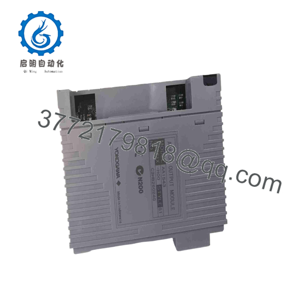
AAI543-H00
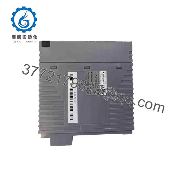
AAI543-H00
Frequently Asked Questions (FAQ)
Can the Yokogawa -H00 be hot-swapped?
Do not assume it can. The safe replacement procedure depends on the specific Yokogawa node architecture and site-approved maintenance procedure. Isolate the applicable power and follow the Yokogawa hardware documentation before removing the module.
What does the H in -H00 mean?
The H indicates the version with digital communication using the HART protocol. The itself provides 16 isolated 4-20 mA analog outputs.
What does the final 00 configuration mean?
For this model designation, the first 0 represents the standard switch-over response in a redundant configuration, while the second 0 identifies the basic type. Other suffix combinations can specify fast switch-over or environmental/explosion-protection options, so suffixes should be checked carefully.
Can -H00 replace another module?
Not automatically. The base function may be similar, but suffixes can define HART capability, redundancy response, environmental options, and other configuration details. Compare the complete part number against the existing installation and Yokogawa documentation before substitution.
Will removing the module erase the control-system program?
is an I/O module rather than the primary control processor. Removing it does not normally mean that the FCS application program itself is erased. However, I/O configuration and channel assignments must remain consistent with the installed hardware. Always preserve a current system configuration backup before maintenance.
What load resistance can the output drive?
The documented allowable load resistance is 0-750 Ω. The connected loop resistance, including wiring and field-device requirements, should remain within the applicable limit.
Is the same as a refurbished unit?
No. New Original/New Surplus and Refurbished/Tested are different commercial conditions. Do not rely on a product listing alone; confirm the actual physical condition, original packaging, serial/traceability information, test documentation, and warranty terms with the supplier before purchase.



