
 WhatsApp: +86 16626708626
 Email:
  Phone: +86 16626708626
Description
Key Technical Specifications
| Parameter | Value |
|---|---|
| Manufacturer | Yokogawa |
| Model | ADV551-P50 |
| Product Type | Isolated digital output module |
| Supported System Family | CENTUM VP, CENTUM CS 3000, CENTUM CS 1000, FIO node and field control unit installations |
| Output Channels | 32 |
| Output Type | Transistor contact, current-sink / NPN output |
| Rated Applied Voltage | 24 V DC |
| External Field Supply | 24 V DC, 50 mA nominal |
| External Supply Range | 20.4–26.4 V DC |
| Load Voltage | 24 V DC, 50 mA nominal |
| Maximum Load Current | 100 mA per channel at 26.4 V DC |
| Output ON Voltage | 2 V DC maximum |
| OFF-State Leakage Current | 0.1 mA maximum |
| Output Isolation | 2 kV AC for 1 minute between output signal and system; 500 V AC for 1 minute between commons |
| Output Response Time | 3 ms or less for status output |
| Mixed Output Response Time | 10 ms or less for mixed status and pulse outputs |
| Pulse Width Range | 8 ms to 7,200 s |
| Pulse Width Resolution | 8 ms; up to 1 ms additional ON/OFF delay |
| Output Functions | Status output, pulse-width output, time-proportional ON/OFF output |
| Backplane Power Consumption | 700 mA maximum at 5 V DC |
| External Supply Consumption | 60 mA maximum |
| Status Display | No status display |
| Explosion Protection | No explosion protection |
| Standard Suffix Meaning | P = pulse-width/time-proportional output; 5 = no status display and no explosion protection; 0 = basic type |
| Connection Options | Dedicated AKB331 cable, MIL connector cable, pressure-clamp terminal block, or optional surge-absorber terminal block |
| Approximate Weight | 0.20 kg / 0.44 lb |
| Redundancy | ADV551 supports dual-redundant configuration when installed in a compatible Yokogawa system |
| Lifecycle Note | Verify node type, terminal adapter, suffix, and installed system revision before ordering |
Yokogawa specifies the ADV551 as a 32-channel, 24 V DC isolated digital-output module with current-sink transistor outputs. The -P50 suffix identifies pulse-width/time-proportional output capability, no status display, no explosion protection, and the basic-type configuration.
Product Introduction
The Yokogawa ADV551-P50 is a 32-channel isolated digital output module used in CENTUM VP, CENTUM CS 3000, and related FIO-based DCS installations. It switches 24 V DC field loads through current-sink transistor outputs, making it suitable for solenoid valves, relay interposing circuits, annunciators, lamps, permissive circuits, and other discrete process-control devices.
This version provides pulse-width and time-proportional ON/OFF functions in addition to normal status output, so it is often selected where the DCS must issue timed pulses or duty-cycle outputs. It does not include local channel status indication. Confirm the field-load polarity, terminal-unit option, node/backplane type, redundancy architecture, and existing engineering configuration before installing a replacement.
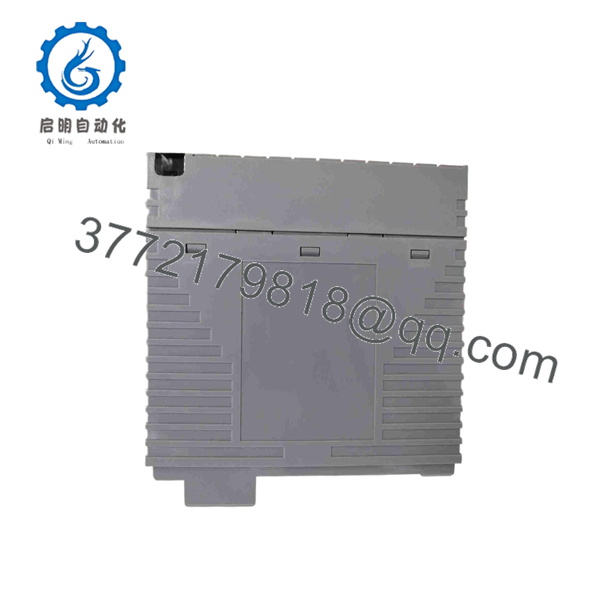
ADV551-P50
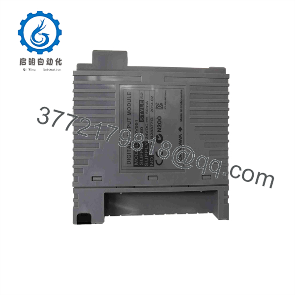
ADV551-P50
Troubleshooting Quick Reference
| Symptom | Possible Cause | Relevance to this Part | Quick Check Method | Recommendation |
|---|---|---|---|---|
| No outputs operate on the entire module | Missing external 24 V DC supply, module not seated, FIO node fault, blown field fuse | ⚠️ Medium | Measure 20.4–26.4 V DC at the module’s external field-supply terminals; verify the FIO node health and inspect supply fuses | Confirm field power and node status before replacing the ADV551-P50 |
| DCS command turns ON but field load remains off | Wrong sinking-output wiring, open field load, missing +24 V supply to load, failed output channel | ⚠️ Medium | Measure +24 V DC at the load, then measure the module output terminal relative to the negative common while commanding the point ON | The load must be wired between +24 V DC and the current-sink output. Correct external wiring before replacing the module |
| Output load stays energized when DCS command is OFF | Shorted output transistor, wiring bypass, forced software point, cross-wired terminal block | ⚠️ Medium | Remove the field conductor under approved conditions; clear software force; measure output terminal state with command OFF | If the terminal remains pulled low with the field wiring disconnected and no software force active, replace the output module |
| Multiple outputs in one group fail together | Common return open, external 24 V DC supply failure, terminal-adapter issue, damaged cable | ❌ Low | Check group common wiring, terminal-block condition, field supply voltage, and cable continuity | Investigate shared field wiring first. Simultaneous multi-channel failure is usually external to the card |
| Output drops out when a solenoid energizes | Coil inrush too high, shorted actuator, supply voltage sag, insufficient suppression | ⚠️ Medium | Monitor 24 V DC at the field terminals during energization; measure coil resistance and inrush current; inspect flyback suppression | Repair the field device or power circuit. Do not use the module to drive a load beyond its 100 mA/channel rating |
| Output point is ON but valve does not move | Failed solenoid coil, stuck valve, open cable, missing pneumatic or hydraulic utility | ❌ Low | Measure voltage across the coil, compare coil current with expected value, and verify mechanical process conditions | The DCS card may be healthy. Check the final element and utility supply before replacing the module |
| Timed pulse is too short, too long, or absent | Incorrect pulse configuration, output function mismatch, scan/engineering configuration issue | ⚠️ Medium | Review the configured pulse value and output function; compare commanded timing with measured output using a scope or timer | Verify application engineering. The module supports 8 ms to 7,200 s pulse widths with 8 ms resolution |
| Output point does not respond quickly enough | Mixed status/pulse output mode, application timing expectation incorrect | ❌ Low | Measure actual transition time at the terminal; compare against the 3 ms status-output and 10 ms mixed-output specifications | Use the appropriate output mode. Do not use a standard DCS transistor output for a sub-millisecond motion or high-speed counting application |
| New module shows no channel status LEDs | Incorrect expectation | ❌ Low | Check the front-panel suffix and compare with the removed unit | The 5 suffix means no local status display. Use DCS diagnostics and field measurements instead |
| Replacement module causes output mapping mismatch | Wrong slot assignment, incorrect database download, terminal block moved, I/O channel mapping error | ✅ High | Compare the old module location, FCS/FIO engineering database, terminal-block labels, and channel numbers before energizing loads | Verify point mapping one channel at a time with loads isolated. Do not energize a full output group on first startup |
| Redundant output pair reports mismatch | Partner module fault, redundancy configuration issue, differing module/suffix revision, bus communication problem | ⚠️ Medium | Confirm both ADV551 modules match the approved redundancy configuration; review DCS diagnostics and field voltage | Check the companion module and engineering configuration. supports dual redundancy only in compatible system designs |
| Module appears dead after cabinet work | ESD damage, partially seated module, bent connector, incorrect terminal adapter installed | ⚠️ Medium | Power down under procedure, inspect rear connector and module guide rails, reseat the card, and verify terminal adapter part number | Replace only after inspecting physical installation. Never force an FIO module into a mismatched terminal arrangement |
| Field output reads a small voltage when OFF | Normal leakage current, high-impedance meter effect, external backfeed | ❌ Low | Measure current through a suitable test load rather than relying only on a high-impedance meter | OFF-state leakage is specified up to 0.1 mA. Use an interposing relay or proper load interface if the load is sensitive to leakage |
❗ Sinking-output warning: The -P50 is a current-sink/NPN output card. Wire the field load between the positive 24 V DC supply and the module output. If the site uses PNP/sourcing output logic, this is not the correct electrical interface.
❗ Load-current warning: The maximum output rating is 100 mA per channel at 26.4 V DC. Do not drive high-current solenoids, contactor coils, heater circuits, or motor loads directly. Use an interposing relay, fused interface module, or properly rated external driver.
❗ No-LED warning: The -P50 configuration does not have local status display. A dark front panel is normal. Confirm point state through CENTUM diagnostics, terminal measurements, and known-safe field tests.
❗ Replacement warning: Take photos of the module, terminal adapter, wiring, node/rack position, and DCS point list before extraction. I have seen a single terminal block shifted one position during a turnaround create hours of false “bad output card” troubleshooting.
If diagnostics remain unclear, provide technical support with the full model label, module location, FIO/node type, terminal-adapter part number, DCS point name, command state, measured 24 V DC field voltage, load type, and photos of the related wiring.
Frequently Asked Questions
What does the Yokogawa -P50 do?
The -P50 provides 32 isolated 24 V DC transistor outputs for Yokogawa FIO-based DCS systems. It uses current-sink outputs to operate discrete field loads such as solenoids, relays, annunciators, lamps, and interface relays. It also supports pulse-width and time-proportional ON/OFF output functions.
I a sourcing or sinking output module?
It is a current-sink, NPN-type output module. The field load normally connects from +24 V DC to the module output point; when the output turns ON, the module sinks current to the field common. Verify the polarity of the existing panel wiring before ordering or installing a replacement.
What does the -P50 suffix mean?
The suffix has specific meaning:
P: Pulse-width output function and time-proportional output function5: No local status display and no explosion protection0: Basic type
Do not replace it with a similar suffix unless you confirm status-display, environmental, explosion-protection, output-function, and terminal-interface requirements.
Can I us for pulse outputs?
Yes. It supports pulse widths from 8 ms to 7,200 s with 8 ms resolution. Yokogawa specifies up to 3 ms response time for normal status output and up to 10 ms for mixed status/pulse output operation. This is suitable for process-control timing and time-proportional functions, not for high-frequency motion control or precision pulse-train generation.
Can I hot-swa?
Use only the hot-swap procedure approved for your installed Yokogawa node, field control unit, and plant operating rules. Before removal, check whether the point is part of a permissive, shutdown, sequence, or control loop. Isolate or force outputs only under an approved work permit, because extracting a digital-output card can change field states and create an unwanted process action.
Ca be used in a redundant arrangement?
Yes, the family supports dual-redundant configuration in compatible Yokogawa installations. Redundancy requires the correct hardware arrangement, matching module type, approved engineering configuration, and commissioning checks. A second module alone does not create redundancy.
Why does an output have voltage present when it is OFF?
First, check whether you are measuring a normal field-side voltage through the load or a real unwanted current path. The module’s specified OFF-state leakage is up to 0.1 mA, and a high-impedance meter can show a voltage even when there is not enough current to energize the load. If a sensitive relay or interface device falsely activates, use the correct load interface or an interposing relay.
Why is this unit less expensive than a current factory-supplied module?
New-surplus modules often come from project overstock, shutdown spares, distributor inventory, or system migrations. The price can be lower because the unit is not sourced through the current OEM channel. Verify the full suffix, production date, packaging condition, terminal-interface requirements, actual photos, warranty, return policy, and stock status before purchase.
What condition should I request for a critical DCS spare?
Request New Original / New Surplus with photos of the Yokogawa label, complete suffix, packaging, connector edge, and any installed option interface. If purchasing Refurbished (tested), request a written test report covering FIO recognition, all 32 output points, field-supply operation, current-sink behavior, pulse-width timing, isolation checks, and sustained load testing. Test photos and videos should be available on request.



