
 WhatsApp: +86 16626708626
 Email:
  Phone: +86 16626708626
Description
Key Technical Specifications
| Parameter | Value |
|---|---|
| Manufacturer | Yokogawa |
| Model | AIP571 |
| Front Identification | BUS1 |
| Product Type | Electrical transceiver for Remote I/O communications |
| Primary Function | Provides the electrical communication interface between a Yokogawa FCU or RIO network path and remote I/O hardware |
| System Family | Legacy Yokogawa CENTUM CS / CENTUM VP Remote I/O architecture |
| Network Application | RIO bus / ESB bus remote I/O communications |
| Bus Assignment | BUS1 path; pair with the corresponding BUS2 unit in redundant architectures |
| Communication Direction | Bidirectional controller-to-remote-I/O data exchange |
| Installation Location | Yokogawa remote I/O node, rack, or compatible control-system interface location |
| Backplane Interface | System rack/backplane connection; verify rack and node configuration before installation |
| Field I/O Function | No direct analog or digital field I/O channels |
| Direct Field Wiring | None; this is a communications interface, not an input/output card |
| Redundancy Role | Supports a dual-path remote-I/O communications architecture when installed with matching BUS2 hardware |
| Style Variants | AIP571 Style S1 and S2 variants are encountered; confirm exact installed style before purchase |
| Module Identification | Verify full front label, BUS1 marking, style code, and rear connector configuration |
| Approximate Market Weight | 0.45–0.47 kg |
| Lifecycle Status | Legacy / stock-dependent spare; preserve existing network topology and configuration records |
The Yokogawa AIP571 is identified in multiple industry sources as an electrical transceiver RIO I/O module for linking remote I/O equipment with a Field Control Unit or another system interface. The BUS1 front marking identifies its role on the first communications path and should not be treated as a generic analog I/O designation.
Product Introduction
The Yokogawa AIP571 BUS1 is an electrical transceiver module used in legacy CENTUM remote-I/O installations. It provides a bidirectional communications path between the Field Control Unit, remote I/O node, and related RIO/ESB bus hardware. The module does not measure analog signals or switch discrete loads; it carries the system-level communications required for remote I/O modules to exchange process data and diagnostics with the controller.
The BUS1 marking matters. In a redundant remote-I/O configuration, and BUS2 form separate communication paths. Replacing a module with the wrong bus-position unit, incorrect style, or incompatible rack interface can leave the node degraded or fully offline. Match the AIP571 style, bus designation, rack location, and paired transceiver arrangement before ordering.
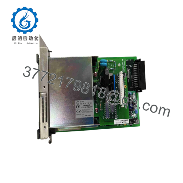
AIP571 BUS1
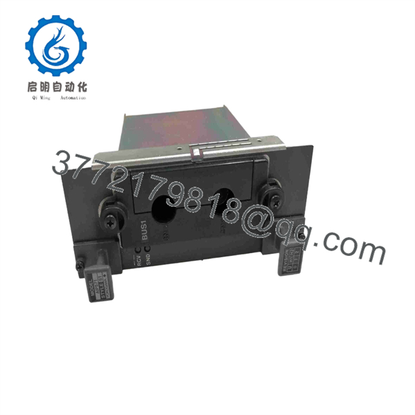
AIP571 BUS1
Troubleshooting Quick Reference
| Symptom | Possible Cause | Relevance to this Part | Quick Check Method | Recommendation |
|---|---|---|---|---|
| Entire remote I/O node is offline | FCU communication failure, RIO/ESB bus cable fault, node power loss, failed AIP571, backplane issue | ⚠️ Medium | Check FCU diagnostics, node power indicators, bus cable continuity, connector seating, and all node-module status LEDs | Verify node power and bus wiring before replacing the |
| communication alarm appears but process control remains online | transceiver fault, cable open, connector contamination, redundant BUS2 path carrying traffic | ⚠️ Medium | Compare and BUS2 diagnostics; inspect cable and connector; confirm the node remains online through BUS2 | Repair the failed path promptly. Redundancy is degraded even if the process continues operating |
| Both and communication paths fail | Node power supply fault, FCU/network fault, rack/backplane fault, major cable issue | ❌ Low | Verify node power and upstream controller communications; inspect both paths independently and review system alarms | Do not replace both units first. Simultaneous dual-path failure is more likely a shared power or controller-side issue |
| I/O point values freeze after cabinet work | partially unseated, damaged bus connector, disturbed remote-I/O cable, rack power interruption | ⚠️ Medium | Use approved shutdown procedures; inspect card seating, backplane connector, cable latching, and node status | Reseat and inspect connections before replacing hardware |
| fault follows the module when swapped under an approved maintenance test | Internal transceiver fault | ✅ High | Perform only under a Yokogawa-approved maintenance procedure; compare diagnostics after moving a known-good equivalent module | If the fault follows the , replace it with the exact matching /style version |
| module is replaced but node remains offline | Wrong style, incorrect bus assignment, incompatible rear connector, unseated terminal/interface hardware, configuration issue | ✅ High | Compare the old and new labels, marking, style code, connector depth, rack position, and paired module | Do not assume all modules are interchangeable. Match the full hardware details |
| Redundancy alarm remains after installing a replacement | fault also present, bus-cable issue, FCU-side interface fault, duplicate configuration problem | ⚠️ Medium | Check each bus path separately and inspect controller-side bus interfaces; review redundancy diagnostics | Replace only the confirmed failed component. Diagnose the full redundant path end-to-end |
| Remote I/O node intermittently drops offline | Loose cable, oxidized connector, poor grounding, cabinet vibration, power-supply dip | ⚠️ Medium | Monitor node voltage and diagnostics while gently checking connectors under safe conditions; inspect cable strain relief | Correct mechanical and power issues first. Intermittent faults are frequently connector-related |
| New module causes a bus mismatch or configuration error | / transceiver installed in wrong position, wrong style revision, rack slot error | ✅ High | Compare slot labels and system drawings; verify the module is in the exact location and its partner remains in | Restore the correct physical arrangement before applying full process control |
| has no apparent front-panel I/O response | Incorrect expectation | ❌ Low | Review the system diagnostics rather than searching for analog input/output channel behavior | This is a communications transceiver, not an analog or digital I/O card |
| One remote node fails while other nodes remain healthy | Local , local node power, branch cable, or local backplane fault | ⚠️ Medium | Compare the affected node against a working node; check local supplies, cables, and transceiver status | Focus on the local node before investigating the entire FCU network |
| A replacement module does not fully seat | Wrong style, damaged guide rail, incompatible connector depth, bent pins | ✅ High | Stop installation; inspect the old unit, new unit, rack guides, and connector geometry | Never force the module. Source the matching style and inspect for connector damage |
| Diagnostics show communication errors after a new cable is installed | Incorrect cable type, damaged cable, wrong connector termination, pinout error | ❌ Low | Verify the cable part number, length, connector type, pinout, and termination against the Yokogawa system documentation | Correct cabling first. Communications modules are often blamed for cable-installation errors |
❗ / warning: Do not install a transceiver into a location—or vice versa—without the approved system documentation. In a redundant remote-I/O node, the bus paths are not merely duplicate labels; they are part of the redundancy and fault-diagnostic architecture.
❗ No-I/O warning: The is not a 16-channel analog card, a 24 V DC I/O card, or a power supply. It is a remote-I/O communications transceiver. If only one field signal is wrong while all other node signals work, start with the actual analog/digital I/O module, transmitter, actuator, wiring, or terminal unit.
❗ Style warning: Style S1 and Style S2 hardware appears in the field. Confirm the existing module’s full label, style code, connector arrangement, and system compatibility before purchasing a spare. Similar front labels do not guarantee an interchangeable unit.
❗ Replacement warning: Photograph the full module label, rack position, / placement, connectors, paired module, node LEDs, and active alarms before removal. I have seen a working redundant node lose both paths because the two modules were returned to opposite bus positions after maintenance.
If troubleshooting remains unresolved, provide technical support with photos of the label, paired module, FCU/node location, cable and connector details, module LEDs, controller diagnostics, rack layout, and the exact error or redundancy alarm history.
Frequently Asked Questions
What does the Yokogawa do?
The is an electrical communications transceiver for Yokogawa remote-I/O systems. It provides the communication path between remote I/O hardware and the Field Control Unit or another compatible remote-I/O interface. It does not directly read sensors or drive actuators.
Is the an analog input module?
No. Despite some inaccurate marketplace descriptions, the is a RIO communications transceiver. It has no direct 4–20 mA, RTD, digital-input, or digital-output channels. Field signals are handled by separate Yokogawa I/O modules installed in the same remote-I/O system.
What does mean on the front of the module?
identifies the module’s role on the first remote-I/O communications path. In a redundant system, it normally works with a corresponding path. If fails but remains healthy, the node may continue running while redundancy is lost. Restore the failed path as soon as practical.
Can I use a module in place of ?
Do not assume so. Match the exact existing module label, bus designation, style, rack location, and system documentation. Even where hardware appears physically similar, the installed position and redundancy configuration must remain correct. Treat / replacement as a controlled DCS maintenance activity.
Can I hot-swap an ?
Follow only Yokogawa-approved procedures for the exact installed CENTUM CS or CENTUM VP remote-I/O node. If the system has confirmed healthy redundancy, an approved maintenance process may allow service of one path; however, do not remove a module casually. Verify health, process risk, active bypasses, node status, and maintenance authorization first.
Why does a alarm appear while the plant keeps running?
The remote-I/O node may be operating through the redundant path. That is useful for avoiding an immediate outage, but it means you have no remaining communication redundancy. Investigate the module, cable, connectors, and controller-side interface promptly. A second fault can take the node offline.
What must I document before replacing the ?
Record the full part number, style code, marking, rack/node location, paired part number and position, system type, active diagnostics, cable type, cable route, connector condition, redundancy status, and controller software/project revision. Take photos before removal. This documentation prevents the most common mistake: restoring a good module to the wrong bus location.
Is the obsolete?
The belongs to a legacy Yokogawa CENTUM remote-I/O family, and stock should be treated as limited and revision-dependent. For a critical system, maintain matched / spares, protect them in ESD-safe packaging, and retain current wiring drawings, rack diagrams, system backups, and controller diagnostic records.
What condition should I request for a production-critical spare?
Request New Original / New Surplus with full label, designation, style code, connector, and packaging photos. For Refurbished (tested) stock, request evidence of power-up, system-rack recognition, communications, redundancy diagnostics, sustained operation, and compatible node testing. Confirm exact stock, lead time, written warranty, and return policy before placing the order.



