
 WhatsApp: +86 16626708626
 Email:
  Phone: +86 16626708626
Description
Key Technical Specifications
| Parameter | AKB335-M005 |
|---|---|
| Model | AKB335 |
| Suffix | -M005 |
| Manufacturer | Yokogawa Electric Corporation |
| Product Type | Signal Cable |
| Cable Configuration | 50-pin to 50-pin |
| Cable Length | 5 m |
| Primary Application | FIO signal connection |
| System Association | CENTUM VP / Yokogawa FIO |
| Operating Temperature | -20 to 70 °C |
| Optional /NL | Supports CSA Non-Incendive instrumentation |
| Cable Length Tolerance | +5%, -0% for reference dimensions ≤3,000 mm |
| Connector Assembly | Factory-terminated signal cable |
Yokogawa’s official general specification lists AKB335 as a Signal Cable (50-50 pins) and defines -M005 as the 5 m cable-length suffix. The same document lists /NL as the option supporting CSA Non-Incendive instrumentation.
The documentation also specifies use within a -20 to 70 °C temperature environment.
Product Introduction
The Yokogawa AKB335-M005 is a factory-terminated 50-pin-to-50-pin signal cable with a nominal 5 m length, designed for Yokogawa FIO signal connections. Yokogawa documentation specifically identifies AKB335 as a signal cable used for connection between FIO equipment and terminal-board assemblies.
For replacement work, the key identification points are the AKB335 model, -M005 length suffix, 50-50 pin configuration, and connector arrangement. The optional /NL version should be specified when CSA Non-Incendive instrumentation support is required.
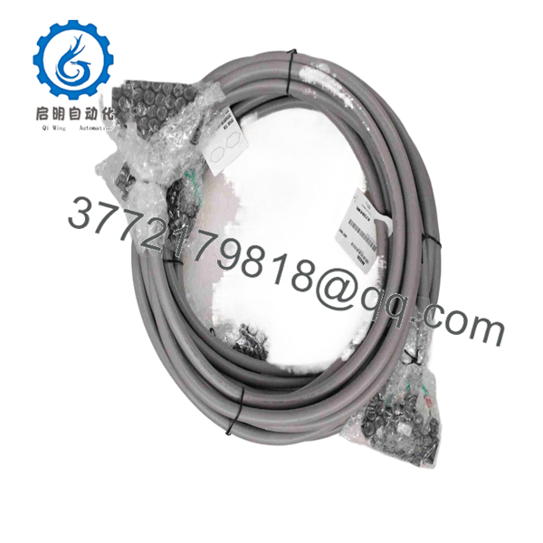
AKB335-M005
Installation & Configuration Guide
Stage 1 — Pre-Installation Preparation (~10 min)
- Confirm the installed cable is marked or documented as .
- Verify the complete part number: .
- Confirm that the required cable length is 5 m.
- Check both mating connectors and terminal-board interfaces for compatibility.
- Review the applicable FIO and terminal-board wiring drawings before removal.
- If the installation requires hazardous-area certification, verify whether /NL is required.
⚠️ Do not substitute AKB331, AKB332, or another Yokogawa cable simply because it has the same connector family. The model number identifies the intended FIO connection.
Stage 2 — Removing the Old Cable (~5 min)
- Place the affected DCS/I/O equipment in the approved maintenance state.
- Follow the plant’s isolation procedure before disconnecting field or I/O signal wiring.
- Identify both ends of the existing cable.
- Label the cable position and connector locations.
- Disconnect the 50-pin connectors using the applicable connector procedure.
- Inspect the connectors for bent pins, contamination, corrosion, or mechanical damage.
Stage 3 — Installing the New Cable (~5 min)
- Verify that the replacement is , not merely another 50-pin Yokogawa cable.
- Check the cable jacket and connector bodies for shipping damage.
- Route the 5 m cable without excessive bending or mechanical tension.
- Connect each 50-pin connector to its designated mating interface.
- ⚠️ Do not force a connector into position. Confirm keying and alignment first.
- Secure the cable so that vibration or pulling force is not transferred to the connector.
- Maintain the cable separation and routing specified by the plant’s DCS installation standard.
Stage 4 — Power-On & Testing (~10–15 min)
- Restore the affected system according to the approved startup sequence.
- Check for communication or I/O diagnostic alarms.
- Verify the expected FIO channels from the engineering or maintenance station.
- Confirm representative input/output signals at the terminal-board side.
- Check for intermittent channel faults that could indicate a connector seating problem.
- Compare channel status with the pre-maintenance condition.
- Document the installed cable model and length in the maintenance record.
FAQ
What is Yokogawa -M005?
It is a 5 m Yokogawa signal cable with 50-pin connectors at both ends. Yokogawa specifies as a 50-50 pin signal cable and assigns to the 5 m length.
What does the – suffix mean?
– means a 5 m cable length. Yokogawa’s specification lists with two standard lengths: -M002 for 2 m and – for 5 m.
Is – used with Yokogawa FIO?
Yes. Yokogawa documentation identifies as a signal cable for FIO-related connections, including connection between an FIO unit and terminal-board assembly.
Is – the same as -/NL?
No. adds the /NL option for CSA Non-Incendive instrumentation. If the installation requires that option, the complete suffix should be matched when ordering.
What is the specified operating temperature?
Yokogawa specifies the cable for a temperature environment of -20 to 70 °C.
Can with another 50-pin cable?
Not based on connector count alone. The cable is part of a defined Yokogawa FIO connection system. Confirm the model, pin configuration, cable length, connector arrangement, and required option code before substitution.
a 24 V power cable?
No. It is documented as a signal cable, not a dedicated 24 V power cable. Some commercial shipping records describe the product using a 24 V classification, but that should not be interpreted as its functional specification. The Yokogawa documentation identifies as a 50-50 pin signal cable.



