
 WhatsApp: +86 16626708626
 Email:
  Phone: +86 16626708626
Description
Key Technical Specifications
| Parameter | Value |
|---|---|
| Manufacturer | Yokogawa |
| Full Model | ALE111-S51 |
| Product Type | Ethernet Communication Module |
| Primary System | Yokogawa ProSafe-RS Safety Control System |
| Compatible Mounting Units | SSC600, SSC500, SSC570 Safety Control Units; SNB10D Safety Node Unit |
| Safety-System Function | Provides Ethernet communication from a Safety Control Station to external systems |
| Physical Ethernet Interface | IEEE 802.3 10BASE-T |
| Ethernet Speed | 10 Mbps |
| Duplex Mode | Half-duplex |
| Network Connection | Point-to-point |
| Ethernet Connector | One RJ-45 port |
| Network Media | 100 Ω unshielded twisted-pair cable |
| Maximum Segment Length | 100 m between the SCS and external system or hub |
| Media Access Method | CSMA/CD |
| Modbus Function | Modbus TCP slave communication |
| DNP3 Function | DNP3 slave communication |
| Modbus Standard | OPEN Modbus/TCP Specification Release 1.0 |
| Modbus TCP Connections | Maximum 2 connections per SCS |
| Modbus Transactions | One transaction per connection |
| Module Current Consumption | 0.5 A |
| Approximate Module Weight | 0.3 kg / 0.66 lb |
| Required Hardware Revision | ALE111 Style S1 and unit revision U:2 or later |
Suffix -S |
Standard type |
Suffix 5 |
No explosion protection |
Suffix 1 |
ISA Standard G3 environmental option |
| Mounting Restriction | Install only in approved SCS or SNB10D node-unit locations |
| Lifecycle Note | Verify module style, unit revision, SCS/SNB compatibility, approved ProSafe-RS software version, and external communication design before installation |
Yokogawa specifies the ALE111-S51 as a 10BASE-T Ethernet communication module for ProSafe-RS safety control systems. It provides Modbus TCP slave and DNP3 slave communications through one RJ-45 port at 10 Mbps half-duplex, supports a 100 m twisted-pair segment, and consumes 0.5 A. Yokogawa requires Style S1 and unit revision U:2 or later for this use.
Product Introduction
The Yokogawa ALE111-S51 is an Ethernet communication module for ProSafe-RS Safety Control Stations and associated SNB10D safety node units. It provides a controlled Ethernet interface for exposing approved safety-system data to external equipment through Modbus TCP slave or DNP3 slave communications. It installs on compatible SSC600, SSC500, SSC570, or SNB10D hardware connected through the ESB bus.
This is not a general-purpose CENTUM Vnet/IP interface and not a 100BASE-TX module. The ALE111-S51 uses one 10BASE-T, 10 Mbps half-duplex RJ-45 port. Confirm the external protocol, port settings, SCS configuration, cable length, module revision, and safety-system change-control requirements before replacement. Any modification to a safety-system communication path requires an approved engineering and functional-safety review.
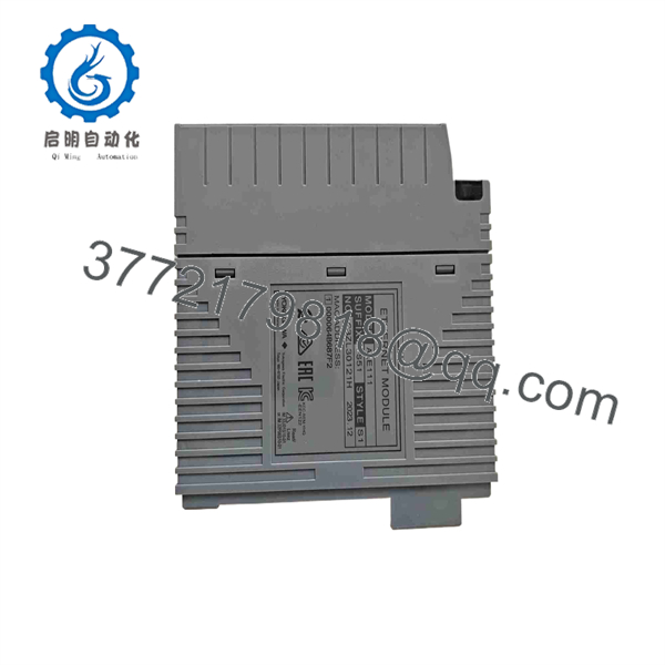
ALE111-S51
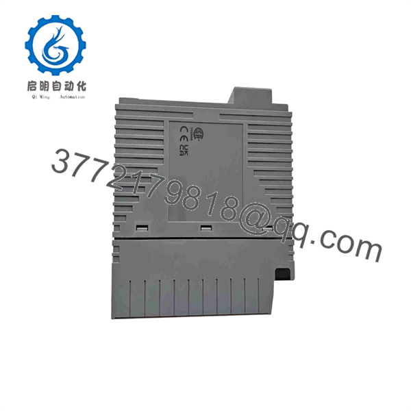
ALE111-S51
Troubleshooting Quick Reference
| Symptom | Possible Cause | Relevance to this Part | Quick Check Method | Recommendation |
|---|---|---|---|---|
| ALE111-S51 is not recognized by the Safety Control Station | Module not seated, unsupported slot, incompatible SCS/SNB unit, old unit revision, hardware configuration mismatch | ⚠️ Medium | Confirm the module is installed in an approved SSC600, SSC500, SSC570, or SNB10D location; verify Style S1 and unit revision U:2 or later | Confirm compatibility and module seating before replacing the -S51 |
| No Ethernet link indication | Damaged cable, incorrect switch port, wrong cable type, inactive port, failed module port | ⚠️ Medium | Inspect the RJ-45 connection; test with a known-good 100 Ω twisted-pair cable; verify switch-port link status and speed configuration | Force the switch port to 10 Mbps half-duplex if autonegotiation does not establish a link |
| Ethernet link is present but Modbus TCP client cannot connect | Incorrect IP address, blocked TCP port, client configuration error, maximum connections reached | ⚠️ Medium | Verify SCS network settings, client IP/subnet, switch VLAN, firewall rules, and Modbus TCP port configuration | Check the two-connection limit and remove stale client sessions before replacing hardware |
| Modbus client connects but receives no valid data | Incorrect register mapping, wrong byte/word order, unconfigured safety data, application download mismatch | ⚠️ Medium | Compare client register addresses and data types with the approved ProSafe-RS communication definition; test one known status bit | Correct the communication map before replacing the module. A live connection does not prove the data model is correct |
| DNP3 SCADA station cannot poll data | DNP3 slave settings incorrect, IP routing issue, incompatible client configuration, network security restriction | ⚠️ Medium | Verify point map, IP settings, station configuration, and event-class settings in the approved engineering database | Review the safety communication design and point configuration before changing hardware |
| Communication works intermittently | Duplex mismatch, switch errors, bad cable, EMC noise, duplicate IP address, network congestion | ⚠️ Medium | Check switch-port error counters, duplicate-IP alarms, cable quality, grounding, and Ethernet port configuration | Use a dedicated industrial switch port configured for 10 Mbps half-duplex as specified by Yokogawa |
| Switch port shows collisions or excessive errors | Full-duplex switch setting, speed mismatch, poor cable, excessive segment length | ❌ Low | Review port settings and collision counters; verify cable run is within 100 m and uses the specified twisted pair | Match the ’s 10 Mbps half-duplex operation. Do not configure the connected port as forced full duplex |
| External system reports frequent communication timeout | Client polling too aggressive, network delay, more than one transaction per connection, unstable network path | ⚠️ Medium | Review polling rate, transaction count, connection behavior, and Ethernet error statistics | Keep the design within the module limit of one transaction per connection and two connections per SCS |
| Replacement module links but external system remains disconnected | IP address not restored, missing system configuration download, wrong module revision, incorrect switch configuration | ✅ High | Compare old and new module configuration, SCS project, network parameters, and switch settings | Restore the approved project and validate communications under the site’s management-of-change procedure |
| Communication fault occurs after a switch replacement | New switch forces 100 Mbps or full duplex, VLAN/security policy blocks traffic, port configuration changed | ❌ Low | Check port speed/duplex, VLAN assignment, MAC learning, firewall, and cable pinout | Configure the switch to support 10BASE-T half-duThe is not a 100BASE-TX interface |
| Module appears to communicate, but safety logic behavior is wrong | Misunderstanding of communication role, incorrect data mapping, inappropriate use of external data in safety logic | ✅ High | Review the approved safety requirement specification, cause-and-effect matrix, and ProSafe-RS application configuration | Stop and conduct a formal functional-safety review. Do not troubleshoot by forcing safety variables from the external system |
| Ethernet cable was disconnected during operation | External SCADA/Modbus data loss, alarm condition, stale values at external system | ❌ Low | Check SCS diagnostics, external-client timeout behavior, and process impact according to the design basis | Restore the cable and confirm alarm/recovery behavior. The safety application must remain safe without external Ethernet data |
| New module will not seat correctly | Wrong module, damaged rack guide, connector damage, incorrect installation location | ✅ High | Compare the old unit label and rear connector with the replacement; inspect slot guides and connector pins | Do not force installation. Confirm act and approved host-unit location |
| Unknown hardware revision on replacement | Old unit revision below U:2, incompatible firmware/hardware combination | ✅ High | Read the style and unit-revision marking from the module label before installation | Source Style S1, unit revision U:2 or later for the documented ProSafe-RS application |
❗ Safety-system warning:The communicates data from a ProSafe-RS Safety Control Station to external systems. Do not change its configuration, Ethernet addressing, Modbus DNP3 map, or connected switch without approved management-of-change documentation, safety validation, and a tested rollback plan.
❗ Ethernet warning: This module is 10BASE-T, 10 Mbps, half-duplex. A modern managed switch configured for forced 100 Mbps or full duplex can produce link failures, collisions, intermittent polling, or apparent module faults. Verify the physical port settings first.
❗ Protocol-role warning: The module functions as a Modbus TCP slave and slave. It is not a Modbus TCP master, EtherNet/IP scanner, general Ethernet router, or Vnet/IP replacement. Verify the external system’s required role before purchase.
❗ Connection-limit warning: Yokogawa specifies a maximum of two Modbus TCP connections per SCS and one transaction per connection. Do not place multiple uncontrolled SCADA, historian, gateway, and engineering clients directly on the module without confirming the approved architecture.
If troubleshooting remains unresolved, provide technical support with photos ofull label, style and unit revision, host SCS/SNB unit, rack slot, RJ-45 cable, switch-port settings, IP configuration, active ProSafe-RS diagnostics, Modbus or client errors, and the approved communication point list.
Frequently Asked Questions
What does theawa do?
The adds a single Ethernet port to a compatible Yokogawa ProSafe-RS Safety Control Station or SNB10D safety node unit. It allows external systems to communicate with approved safety-system data through Modbus TCP slavd DNP3 slave protocols.
the a standard Ethernet switch or Vnet/IP module?
No. It is a dedicated ProSafe-RS Ethernet communication module with one 10BASE-T port. It is not an Ethernet switch, Vnet/IP interface, EtherNet/IP scanner, or general-purpose network adapter. Its documented functions are Modbus TCP slave and slave communications.
What Ethernet speedthe use?
It uses IEEE 802.3 10BASE-T at 10 Mbps half-duplex. The connection is point-to-point over 100 Ω unshielded twisted-pair cable, with a maximum segment length of 100 m. Configure the connected switch port accordingly if autonegotiation does not work reliably.
the act as a Modbus TCP master?
No. It operates as a Modbus TCP slave. An external Modbus TCP client, such as a SCADA server, gateway, historian, or PLC configured as a client/master, reads from or writes to the approved mapped data. Do not order this unit if your application requires the Yokogawa controller to initiate Modbus polling of external devices.
How many Modbus TCP clients can connect?
Yokogawa specifies a maximum of two Modbus TCP connections per Safety Control Station, with one transaction per connection. Design the communications architecture carefully; if several systems require the same data, use an approved gateway, historian, or supervisory architecture rather than uncontrolled direct connections.
Can I replace ith ?
No. Yokogawa uses in more than one system conThe is the standard, no-explosion-protection, ISA Standard G3 configuration for the cited ProSafe-RS safety-control application. Verify the host system, installed module style, unit revision, environmental requirement, and protocol package before replacing another model.
Can I hotthe ?
Do not assume hot-swapping is allowed. Follow the approved ProSafe-RS maintenance procedure for the installed SCS/SNB hardware. Before removal, assess the external-system impact, confirm safety function independence from Ethernet communication, preserve diagnostics and configuration records, and ensure authorized personnel manage the change.
Why does the switch show a link but communications still fail?
A physical link only proves the cable and electrical layer are active. Check the 10 Mbps half-duplex setting, IP address, subnet, VLAN, firewall policies, Modbus TCP client configuration, point map, register/data type mapping, connection count, and application download. The most common issue is configuration, not a failed RJ-45 port.
Is ALE111-S51 obsolete?
It belongs to an established Yokogawa ProSafe-RS hardware family. Current availability depends on system lifecycle status, geographic support, and available spare inventory. For safety-critical installations, maintain a verified spare with the correct style and unit revision, and keep validated ProSafe-RS project backups, network drawings, switch configurations, communication maps, and functional-safety test records.
What condition should I request for a safety-system spare?
Request New Original / New Surplus with clear photos of the full Yokogawa label, suffix, Style S1, unit revision U:2 or later, RJ-45 port, connector edge, and original protective packaging. For Refurbished (tested) stock, require documented host-rack recognition, 10BASE-T link testing, Modbus TCP slave test, slave test where used, sustained communication testing, and written warranty. Final installation must still follow the approved site safety-validation procedure.



