
 WhatsApp: +86 16626708626
 Email:
  Phone: +86 16626708626
Description
Key Technical Specifications
| Parameter | Specification |
|---|---|
| Model | CP401-10 |
| Manufacturer | Yokogawa |
| Product Type | Processor Module |
| Processor Family | CP401 |
| Processor Architecture | MIPS R5000 32-bit RISC* |
| Main Memory | 32 MB* |
| System Platform | CENTUM CS3000 / compatible CP401 FCS configurations |
| Communication Bus | V net / ESB* |
| Power Supply | 5 V DC* |
| Current Consumption | Approximately 2.6 A* |
| Power Consumption | Approximately 13 W* |
| Operating Temperature | 0 to 55 °C* |
| Operating Humidity | 10–90% RH, non-condensing* |
| Mounting | FCS rack / control-unit installation |
| Dimensions | Approximately 130 × 100 × 42 mm* |
| Weight | Approximately 0.35 kg* |
| Redundancy | Dual-redundant processor configuration supported |
*Publicly available supplier references provide these hardware figures, but the sources are not fully consistent on CP401-10 specifications. Yokogawa documentation confirms the CP401 processor family and its redundant processor architecture, while catalog references specifically identify CP401-10-S1 as a CENTUM CS3000 FCS processor. Verify the complete suffix/style before using these values for engineering replacement.
Product Introduction
The Yokogawa CP401-10 is a processor module used in Yokogawa Field Control Station architectures. It provides the central processing function for control execution and coordinates communication with the associated I/O subsystem. Public catalog references identify the -10-S1 as a processor/CPU module for CENTUM CS3000 FCS applications.
The processor architecture supports redundant operation. Yokogawa technical documentation describes the processor modules using a dual-redundant “Pair & Spare” architecture, with processor results cross-checked to support continued control following a processor fault.
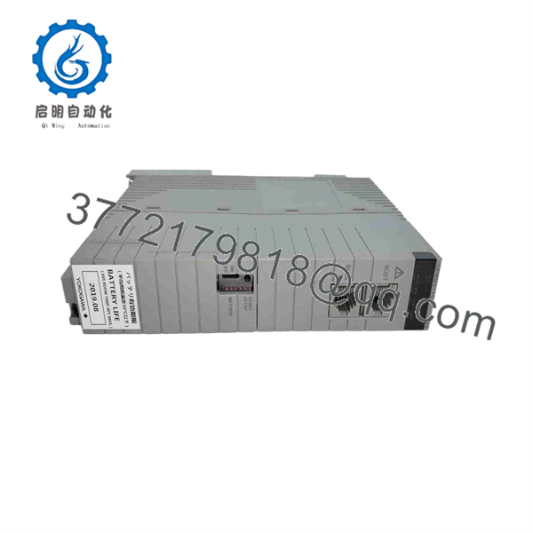
CP401-10
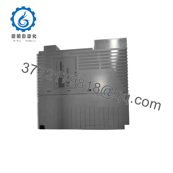
CP401-10
Installation & Configuration Guide
Stage 1: Pre-Installation Preparation — 5–10 Minutes
- ⚠️ Place the affected process in a safe operating state and notify operations before removing the processor.
- Apply LOTO according to the plant procedure.
- Allow the equipment to discharge before touching the module or backplane.
- Prepare:
- ESD wrist strap
- PH1 screwdriver
- Digital multimeter
- Wire labels
- Smartphone or camera
- Record the complete -10 nameplate information, including:
- Style/revision
- Serial number
- Firmware revision
- Hardware revision
- System configuration
- Photograph the installed processor, rack position, connectors, switches, and status LEDs.
- Back up the applicable FCS configuration and control database before replacement.
⚠️ Do not t-S1 as interchangeable based only on the base model. Catalog references specifically distinguish the S1 style.
Stage 2: Removing the Old Module — Approximately 5 Minutes
- Confirm that the FCS has been transferred to the appropriate redundant or maintenance state.
- Verify power isolation where the maintenance procedure requires it.
- Release the processor module retaining mechanism.
- Disconnect the applicable backplane/network connectors without pulling on the cable.
- Remove the module straight from its slot.
- Inspect the backplane connector for bent contacts, contamination, or mechanical damage.
- Keep the rem available for comparison until commissioning is complete.
Stage 3: Installing the New Module — Approximately 5 Minutes
- Wear the ESD strap before handling the replacement processor.
- Verify the exact model, style, hardware revision, and firmware compatibility.
- Compare connector arrangement and module labeling against the removed unit.
- Confirm the replacement belongs to the same FCS hardware generation.
- Insert the module carefully into the designated slot.
- Secure the module using the original retaining mechanism.
- Reconnect all required system connections.
- For redundant configurations, verify that the replacement processor is installed in the correct redundant position.
- Check that no connector is partially engaged.
Stage 4: Power-On & Testing — Approximately 10–15 Minutes
- Before energizing, check the relevant supply rail with a multimeter.
- Power the FCS according to the Yokogawa maintenance procedure.
- Observe the processor status LEDs during startup.
- Confirm that the module completes its startup diagnostics.
- Verify communication with the FCS engineering/HIS environment.
- Check processor redundancy status if the FCS uses a dual configuration.
- Confirm that the expected control database and application configuration are available.
- Verify representative I/O points.
- Check control loops, alarms, sequence logic, and interlocks before returning the FCS to normal service.
- Monitor the processor and system diagnostics after restoration.
Practical troubleshooting notes:
- Processor fails to initialize → check style, firmware, rack position, and backplane condition.
- Redundancy does not establish → compare processor revisions and redundant-pair configuration.
- I/O communication faults → inspect ESB/V net connections and associated interface modules.
- Application unavailable → verify configuration download and nonvolatile program data.
- Unexpected system behavior after replacement → compare the replacement’s hardware/firmware revision with the removed unit before changing control logic.
Yokogawa documentation states that processors use nonvolatile flash memory for application-program retention, while a secondary battery provides additional storage backup.
FAQ
Q1. What is the Yoko?
is a Yokogawa processor module used as the central processing element within applicable Field Control Station architectures. It executes control processing and coordinates the associated I/O and system communication functions.
Q2. Which Yokogawa system uses?
Public catalog references specifically identify as a processor/CPU module for the CENTUM CS3000 Field Control Station. Other supplier references also associate the family with CENTUM VP configurations. Because platform and style references are inconsistent across secondary sources, verify the existing FCS model and complete part number before replacement.
Q3. support processor redundancy?
Yes. Yokogawa’s technical documentation describes processor modules in a dual-redundant configuration using the Pair & Spare architecture. The processor modules perform matching control computations and cross-check results.
Q4. Can I directly repla with any processor?
No. Verify the complete ordering number, style, hardware revision, firmware compatibility, FCS generation, and rack configuratio-S1, for example, is specifically identified as a style-S1 variant in current catalog references.
Q5. Will the control application remain available after processor replacement?
The architecture uses nonvolatile flash memory for application-program storage, but the replacement unit should not be assumed to contain the same application or configuration. Back up the running FCS configuration before removal and follow the applicable Yokogawa recovery/download procedure.
Q6 an obsolete or legacy module?
It should be treated as a legacy Yokogawa processor module for maintenance and replacement planning. Current catalog listings continue to iden-S1 as spare processor modules, but that does not establish current OEM production status.
Q7. What information should I provide when sourcing a replacement?
Provide the complete part number, style code, hardware revision, firmware revision, serial number, and a clear nameplate photograph. For an operating CENTUM system, also provide the FCS model and processor-pair configuration. This prevents a visually similar processor from being installed into an incompatible hardware generation.



