
 WhatsApp: +86 16626708626
 Email:
  Phone: +86 16626708626
Description
Key Technical Specifications
| Parameter | Value |
|---|---|
| Manufacturer | Yokogawa Electric Corporation |
| Model | EB401-10 |
| Product Type | ER Bus Interface Master Module |
| Application | Field Network I/O (FIO) |
| ER Bus Interface | IEEE 802.3 10BASE-2 |
| Communication Speed | 10 Mbps |
| Physical Connector | BNC |
| ER Bus Transmission Distance | Maximum 185 m with YCB141 cable |
| Current Consumption | 0.7 A |
| Weight | Approximately 0.3 kg |
| Dimensions | 32.8 × 144.65 × 125.5 mm |
| Redundancy | Dual-redundant configuration supported |
| Installation | ESB Bus Node Unit / applicable FIO Field Control Unit |
| Bus Branching | Up to 4 ER Bus segments from an FCU |
| Associated Accessory | YCB146 T-type connector; YCB148 terminators |
Yokogawa’s specification identifies EB401 as an ER Bus master interface and defines the model suffix system separately from the base EB401 model. It specifies the standard, explosion-protected, and ISA G3 options.
One important identification point: “EB401-10” should not be confused with the suffix-code structure in Yokogawa’s older GS documentation. Before purchasing a replacement, compare the complete nameplate and system configuration rather than relying on the shortened marketplace model description.
Product Introduction
The Yokogawa EB401-10 is an ER Bus Interface Master Module used with Yokogawa FIO architectures. It provides the ER Bus communication interface between applicable Field Control Units or node units and remote ER Bus nodes. Yokogawa documentation specifically lists EB401 as the ER Bus master interface for FIO.
The module uses an IEEE 802.3 10BASE-2 physical layer with a BNC connection and a 10 Mbps communication rate. With the specified YCB141 cable, the published maximum transmission distance is 185 m. modules can also be installed as a pair for dual-redundant ER Bus configurations.
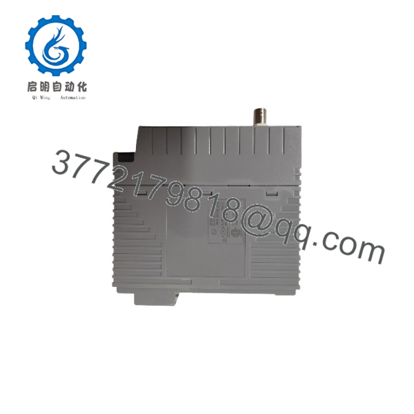
EB401-10
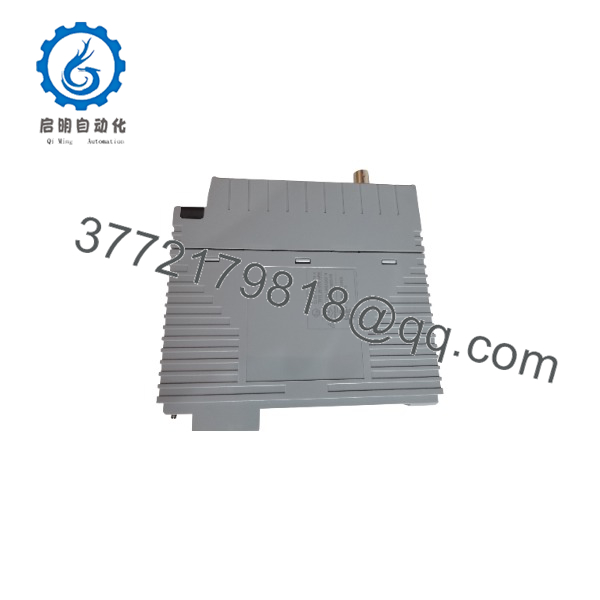
EB401-10
Installation & Configuration Guide
Stage 1: Pre-Installation Preparation — 5–10 minutes
⚠️ Safety First: Put the affected control system into an approved maintenance state and follow the plant’s lockout/tagout procedure. Do not disconnect an active ER Bus connection simply because the module appears to be a communication-only device.
Tools Required:
- ESD wrist strap
- Appropriate screwdriver
- Digital multimeter
- Wire/connector labels
- Smartphone or camera
- Applicable Yokogawa hardware manual
Data Backup:
- Record the complete module nameplate information.
- Photograph the existing installation.
- Photograph the BNC/ER Bus cable routing.
- Record whether the system uses one or two modules.
- Identify the host node type.
- Record the existing system configuration before removal.
Yokogawa’s documentation identifies as an FIO ER Bus master interface and lists it for use with applicable node units.
Stage 2: Removing the Old Module — 5 minutes
- Confirm that the affected node is in a safe maintenance state.
- Isolate power according to the approved site procedure.
- Identify the position before disconnecting anything.
- Label the ER Bus connection and associated wiring.
- Disconnect the BNC connection carefully.
- Release the module’s mounting mechanism.
- Remove the module straight from its slot.
- Inspect the slot connector and surrounding area for contamination or mechanical damage.
⚠️ Do not pull on the coaxial cable itself. The connector and cable assembly should remain mechanically undamaged for correct ER Bus operation.
Stage 3: Installing the New Module — 5–10 minutes
- Verify the exact module identification before insertion.
- Put on an ESD wrist strap.
- Confirm that the replacement module’s environmental and explosion-protection specification matches the existing installation.
- Confirm the correct host node and slot position.
- Insert the into the designated slot.
- Secure the module according to the Yokogawa hardware procedure.
- Reconnect the ER Bus BNC connection.
- Check cable routing and connector seating.
- If the system uses redundant modules, verify both modules and their respective bus paths.
Yokogawa states that can be installed in applicable ESB Bus Node Units or FIO Field Control Units, with two modules providing dual-redundant ER Bus configuration.
Self-Checklist:
- Correct variant verified
- Correct slot verified
- BNC connection secured
- ER Bus cable undamaged
- Redundant module checked if applicable
- Environmental specification verified
- Module seated correctly
Stage 4: Power-On & Testing — 10–20 minutes
- Check the installation before restoring power.
- Restore power according to the site’s approved startup procedure.
- Observe module status indications.
- Confirm that the host FIO/node recognizes the ER Bus interface.
- Verify communication with the connected ER Bus node.
- Check the system diagnostic display for bus-related alarms.
- Verify I/O communication from the affected remote node.
- Confirm that redundant communication operates correctly if a dual configuration is installed.
- Return field devices to service only after communication has been confirmed.
⚠️ Do not use an ordinary Ethernet switch or Ethernet diagnostic procedure to troubleshoot the ER Bus. Although the physical layer is based on IEEE 802.3 10BASE-2, this is an ER Bus interface within Yokogawa’s control-system architecture, not a conventional modern Ethernet network. The published specification identifies the interface specifically as an ER Bus master interface.
Frequently Asked Questions (FAQ)
What is the Yokogawa -10 used for?
The is an ER Bus Interface Master Module for FIO. It provides the interface required to connect applicable Yokogawa Field Control Unit or node-unit architectures to ER Bus remote nodes. Yokogawa’s own documentation lists specifically for this function.
Is -10 a digital I/O module?
No. is a communication/interface module, not a conventional discrete I/O channel module. Some reseller pages incorrectly categorize -10 as a digital I/O module. Yokogawa’s documentation identifies the hardware as an ER Bus Interface Master Module.
Can support redundant ER Bus communication?
Yes. Yokogawa documentation states that two modules can be installed to configure a dual-redundant ER Bus. The actual redundancy behavior depends on the host node architecture and system configuration.
What communication speed does use?
The published specification gives 10 Mbps over an IEEE 802.3 10BASE-2 physical layer. The interface uses a BNC connector, and Yokogawa specifies a maximum transmission distance of 185 m when using YCB141 cable.
Can I connect to standard Ethernet equipment?
No. The 10BASE-2 designation describes the physical-layer technology; it does not mean that can simply be connected to a modern Ethernet switch. is specifically an ER Bus master interface within Yokogawa’s FIO architecture.
Does the suffix matter when replacing an ?
Yes. Yokogawa’s documentation defines suffix codes for different specifications, including standard, explosion-protected, and ISA Standard G3 versions. For a plant replacement, check the complete ordering code and environmental requirements rather than matching only the “” portion.
compatible with every Yokogawa CENTUM system?
Not automatically. Compatibility depends on the specific FIO architecture, node unit, Field Control Unit, bus arrangement, and hardware revision. Yokogawa identifies for FIO applications and documents its use with specific node architectures. Verify the existing host unit and complete Yokogawa ordering code before replacing the module.



