
 WhatsApp: +86 16626708626
 Email:
  Phone: +86 16626708626
Description
Key Technical Specifications
- Model: F3PU10-0N
- Manufacturer: Yokogawa Electric Corporation
- Product Series: FA-M3 Range-free Multi-controller
- Product Type: Dedicated PLC base power supply module
- Input Voltage: 100–240 V AC, single phase, 50/60 Hz
- Permitted Input Range: 85–264 V AC, 50/60 Hz ±3 Hz
- Input Power Consumption: 35 VA
- Inrush Current: 20 A maximum at 120 V AC and 25 °C; 45 A maximum at 240 V AC and 25 °C
- Backplane Output Voltage: 5 V DC
- Rated Output Current: 2.0 A
- Compatible Base Modules: F3BU04-0N and F3BU06-0N 4-slot and 6-slot FA-M3 bases
- Mounting Position: Dedicated power-supply position on the FA-M3 base
- Terminal Hardware: M4 screw terminals
- Status Indication: Power-status LED
- Cooling Method: Natural convection
- Operating Temperature: Verify against the installed FA-M3 cabinet and base-module documentation
- Isolation Check Reference: 5 MΩ minimum at 500 V DC between applicable FAIL-signal contacts and FG terminal
- Primary Use: Supplies regulated backplane power for the FA-M3 CPU, I/O, and communications modules
The current Yokogawa FA-M3 specification identifies the equivalent current model as F3PU10-0S for 4-slot and 6-slot bases, with 100–240 V AC input, 35 VA consumption, and a 5 V DC, 2.0 A rated output. Legacy F3PU10-0N listings identify the same key electrical rating and intended 4-slot/6-slot FA-M3 base application. Confirm the exact suffix, base generation, and terminal arrangement against the installed unit label before purchase.
Product Introduction
The Yokogawa F3PU10-0N is an AC input power supply module for a Yokogawa FA-M3 PLC base. It converts 100–240 V AC mains power into the regulated 5 V DC backplane supply required by the CPU, I/O, and communication modules installed in a compatible 4-slot or 6-slot FA-M3 base.
Use the F3PU10-0N as an exact like-for-like replacement where the installed base and original label match. Its 2.0 A backplane capacity is suitable only when the total base-module current demand remains within rating. Check the rack load before fitting a replacement; a power supply that trips under load is not automatically defective.
Troubleshooting Quick Reference
| Symptom | Possible Cause | Relevance to This Part | Quick Check Method | Recommendation |
|---|---|---|---|---|
| No CPU RUN, no module LEDs, and no power LED | No incoming AC supply, tripped breaker, blown fuse, loose terminal, wrong voltage connection | ❌ Low until input is verified | With approved electrical-safety procedures, measure 85–264 V AC at the F3PU10-0N input terminals; inspect the cabinet breaker, fuse, M4 terminals, and protective-earth connection | Correct supply-side faults before replacing the power module |
| Power LED off but AC voltage is present | Internal power-supply failure, failed input terminal connection, damaged module | ✅ High | Verify voltage directly at the module terminals using a properly rated meter; isolate power, retorque terminals to approved values, then retest | If correct AC is present at the module and the LED remains off, replace with a verified -0N |
| Power LED cycles or CPU resets intermittently | Rack overload, loose AC wiring, supply voltage sag, excessive cabinet temperature, aging power supply | ✅ Medium | Trend AC input while large loads switch; check rack loading; inspect for repeated CPU resets and measure cabinet temperature | Remove nonessential modules or check load calculations; maintain at least a 20% current margin where possible |
| CPU starts but I/O modules remain unpowered | Backplane connection issue, base damage, loose module seating, overloaded 5 V DC rail | ✅ Medium | Power down, inspect the base connector and module seating, then compare installed-module load to the 2.0 A 5 V DC rating | Reseat modules and inspect the base; replace the PSU only after ruling out backplane damage or overload |
| PLC runs until an I/O card is added | Total 5 V DC backplane current exceeds 2.0 A, shorted I/O module, incorrect base application | ❌ Usually rack-load related | Remove recently added modules, then power up one module group at a time; calculate the sum of CPU, I/O, and communication-module current consumption | Reduce load, move modules to another powered base, or select the correctly rated power/base arrangement |
| Cabinet fuse blows when energizing | Input short, wiring error, failed input suppression, internal PSU fault, inrush protection mismatch | ✅ Medium | Isolat, inspect supply wiring, and compare protective-device characteristics with the 20 A/45 A inrush-current specification | Do not install an oversized fuse. Verify wiring and use appropriately rated protection; replace a module only after isolation confirms it causes the fault |
| becomes unusually hot | Cabinet ventilation blocked, ambient temperature high, output overload, aging internal components | ✅ Medium | Check cabinet temperature, air paths, module spacing, and total 5 V load; inspect for discoloration or odor with power removed | Correct heat and overload conditions first. Replace any module with heat damage, odor, or repeat thermal shutdown |
| New replacement does not power the base | Wrong base type, incorrect suffix, connector mismatch, improper seating, input wiring not restored | ✅ Medium | Compare front label, terminal layout, base part number, physical connector, and old-versus-new mounting points before applying AC power | Do not force a near-match part into the base. Obtain an exact compatibility confirmation for the installed FA-M3 base |
| Communication faults begin after replacement | CPU or communication module reset caused by power interruption, loose modules, project battery issue | ❌ Low | Check CPU diagnostics after stable power-up; reseat communication modules and verify controller configuration retention | Address startup diagnostics and module seating before suspecting the replacement power supply |
| Electric shock, ground-fault, or insulation alarm | Damaged incoming wiring, inadequate protective earth, moisture, insulation breakdown | ❌ Usually installation-related | With power isolated, inspect PE connection, input cable insulation, moisture ingress, and terminal contamination; perform insulation testing only per approved procedure | Stop work and correct the electrical installation. Do not megger the powered PLC rack or connected electronics without manufacturer-approved isolation |
❗ Input-power warning: This module accepts 100–240 V AC. Treat it as mains equipment, not 24 V DC PLC power. Lock out the upstream source, verify absence of voltage, and confirm the protective-earth connection before touching terminals.
❗ Rack-load warning: provides 5 V DC at 2.0 A. Before swapping it, total the published 5 V current requirements of every CPU, I/O, communications, and specialty module on the base. Leave practical headroom—20% is a sensible service target. I have seen a replacement PSU blamed for a shutdown when an added communications card had simply pushed the old 2.0 A supply past its limit.
❗ Terminal warning: Take a clear photo of the old input terminals and grounding arrangement before removal. Do not wire from memory. Similar FA-M3 power-supply variants can have different base compatibility and ratings.
If the fault remains unclear, send technical support photos of the module label, compatible base label, terminal wiring, LED state, cabinet supply measurement, and the complete list of installed modules. Keep these checks in mind and you will save yourself most of the usual rework time.
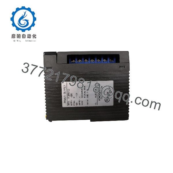
F3PU10-0N
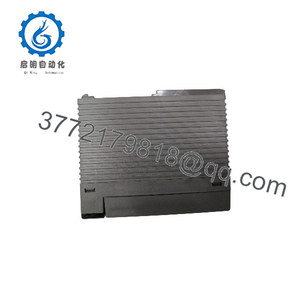
F3PU10-0N
Frequently Asked Questions
What does the Yok do?
supplies regulated backplane power to a Yokogawa FA-M3 PLC base. It takes single-phase 100–240 V AC input and supplies 5 V DC power for the CPU, I/O, communication, and other modules installed on a compatible base. It is not a general-purpose field 24 V DC power supply and should not be used to power sensors, solenoids, or external control circuits.
Which FA-M3 base units us?
is associated with FA-M3 4-slot and 6-slot base configurations, including F3BU04 and F3BU06 family bases. Yokogawa’s current FA-M3 specification lists th10-0S counterpart for F3BU04-0N and F3BU06-0N bases. Confirm the exact installed base part number and the original power-supply suffix before ordering because legacy FA-M3 hardware revisions can differ.
Can I replac with F3PU20-0N or another FA-M3 power supply?
Not as a casual substitution. The F3PU20 family serves different, larger FA-M3 base configurations and has a higher power rating. Even where another supply appears physically similar, base compatibility, connector geometry, mounting, backplane capacity, and operating documentation must match.
For an emergency replacement, use an match whenever possible. If you are considering a newer suffix or different supply family, verify the migration path with Yokogawa documentation or a qualified FA-M3 specialist before energizing the rack.
Can I hot-swa?
No. This is the source of backplane power for the entire PLC base. Removing it live will shut down the CPU, I/O, communications, and any process control handled by that base. Isolate the AC feed using approved lockout/tagout procedures, verify zero voltage at the input terminals, then replace the module.
The bigger concern is process impact. Confirm whether the FA-M3 CPU controls motion, safety interlocks, valves, drives, or remote I/O before removing power. A PLC reboot can create alarms, command loss, or an unplanned process transition.
Will I lose the PLC program when replacing this power supply?
Usually, the CPU program remains in its configured memory, but do not treat “usually” as a maintenance plan. Program retention depends on the CPU type, memory configuration, battery state, and how the project was stored. Back up the FA-M3 application before any planned work, and record CPU diagnostics and battery condition.
After replacement, confirm CPU startup state, RUN/STOP mode, I/O diagnostics, communication links, HMI values, and any retentive data such as recipes, counters, or production totals.
Why does a replac fail immediately after installation?
The common causes are incorrect AC wiring, a rack short, excessive 5 V DC load, a defective I/O module, a damaged base connector, or an incompatible replacement part. To be honest, the power supply itself is often not the root cause. Disconnect nonessential modules, inspect the base, verify the AC input, and rebuild the rack incrementally under controlled conditions.
Do not keep cycling power into a suspected short. Repeated fault energization can damage the base, connected modules, and the replacement supply.
I obsolete, and should I keep a spare?
is a legacy FA-M3 supply, while Yokogawa’s current documentation identifies th10-0S as the current listed 4-slot/6-slot AC supply version. Availability of the exact -0N suffix may therefore depend on New Surplus or tested refurbished inventory. For a production-critical FA-M3 rack, keep a verified spare matched to the exact base type and store it in ESD-safe packaging in a controlled environment.
How should a New Su be tested before shipment?
Start with traceability: inspect the Yokogawa label, suffix, serial label, terminal screws, connector blades, housing, and packaging. Check for corrosion, heat discoloration, cracked plastic, rework marks, or damaged mounting hardware.
For functional testing, install the unit in a genuine compatible FA-M3 4-slot or 6-slot base with a known-good CPU and controlled module load. Apply regulated AC power within the specified range, verify the power-status LED and CPU boot sequence, then monitor stable operation under a measured backplane load below 2.0 A. Use a calibrated meter such as a Fluke 115 to confirm input voltage and inspect for abnormal heating during a sustained run.
Record the test setup, input voltage, installed load, LED status, CPU startup result, and test duration. Perform final inspection, package in ESD-safe material, and protect it with foam and a heavy-duty corrugated box. Test photos and video should be available upon request. The documented rating is 100–240 V AC input, 35 VA consumption, and 5 V DC at 2.0 A for compatible 4-slot and 6-slot FA-M3 bases.



