
 WhatsApp: +86 16626708626
 Email:
 Phone: +86 16626708626
Description
Key Technical Specifications
| Parameter | Value |
|---|---|
| Manufacturer | Yokogawa |
| Model | ISC40G-TF-T1-05 |
| Product Type | General-purpose inductive conductivity sensor |
| Measurement Principle | Inductive / toroidal conductivity |
| Sensor Material | PFA for the TF configuration |
| Temperature Element | Pt1000 |
| Cable Length | 5 m |
| Conductivity Range | 0–2,000 mS/cm at actual process temperature |
| Temperature Range | −20°C to +130°C at 100 kPa |
| PFA Sensor Installation Factor | 3.00 cm⁻¹ nominal |
| PFA Sensor Measurement Error | 1.0 µS/cm sensor error to consider in application selection |
| Temperature Response | t90 < 15 min for PFA sensor |
| Waterproof Rating | IP67 |
| Cable Construction | Multicore shielded cable with two low-noise coaxial conductors and four insulated wires |
| Maximum Functional Cable Length | 50 m when used with the specified extension cable and junction box |
Yokogawa’s current ISC40G documentation confirms the inductive measurement principle, Pt1000 temperature element, PFA construction for the T-series sensor body, 0–2,000 mS/cm operating range, −20°C to +130°C temperature range, IP67 protection, and the 50 m maximum functional cable arrangement.
Model-code caution: Older Yokogawa documentation identifies -TF as the PFA flange-model configuration, while the current 2024 general specification presents the PFA sensor as -TG and lists flange adapters separately. Therefore, do not substitute a current ISC40G-TG configuration solely because the base ISC40G number looks similar. Verify the nameplate, mechanical connection, and existing Yokogawa documentation before ordering.
Product Introduction
The Yokogawa ISC40G-TF-T1-05 is a general-purpose inductive conductivity sensor for continuous liquid conductivity measurement. The configuration uses a PFA sensor construction, Pt1000 temperature element, and 5 m cable. Inductive sensing keeps the measurement coils isolated from direct process contact, which is useful for chemically aggressive process liquids.
The PFA version is intended for applications where chemical resistance is important. Yokogawa specifies conductivity measurement up to 2,000 mS/cm and process temperatures up to 130°C at 100 kPa. The Pt1000 element provides temperature compensation and indication; it is not intended for process temperature control.
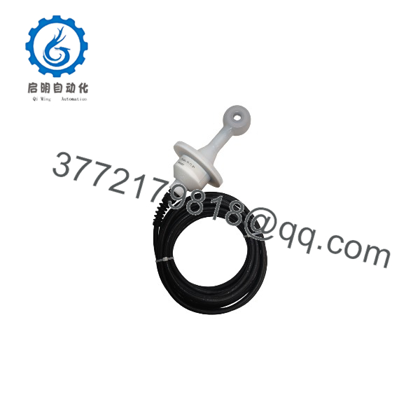
ISC40G-TF-T1-05
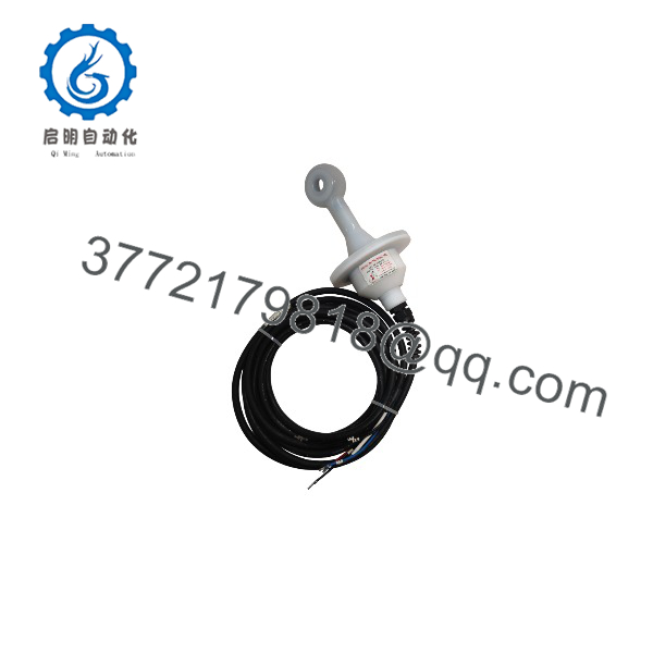
ISC40G-TF-T1-05
Installation & Configuration Guide
Stage 1: Pre-Installation Preparation — approximately 10 minutes
- Notify operations and place the process in a safe maintenance state. Follow the site’s LOTO procedure where isolation is required.
- Confirm that the replacement is exactly ISC40G-TF-T1-05 or an OEM-approved equivalent.
- Photograph the existing sensor wiring before disconnecting anything.
- Record the connected Yokogawa analyzer or converter model and all relevant configuration values.
- Prepare:
- ESD protection
- Appropriate wrench for the sensor/fitting
- Multimeter
- Cable labels
- Camera or smartphone
- Correct replacement gasket/O-ring where required
- Confirm the process connection and mechanical dimensions before removing the existing sensor.
⚠️ Important: Do not assume that a newer suffix is mechanically interchangeable with an older -TF configuration. Yokogawa’s current documentation uses different suffix conventions for the PFA sensor and flange arrangements.
Stage 2: Removing the Existing Sensor — approximately 5 minutes
- Isolate the process connection according to the plant procedure.
- Verify that pressure and temperature are at a safe level before opening the process connection.
- Label each sensor conductor before disconnecting it.
- Disconnect the sensor cable from the analyzer or junction point without pulling on the cable itself.
- Remove the mechanical retaining hardware.
- Withdraw the sensor carefully and inspect the process fitting.
- Check for damaged threads, degraded seals, deposits, or mechanical damage.
Keep the old sensor available until the replacement has passed commissioning.
Stage 3: Installing the New Sensor — approximately 10 minutes
- Inspect the replacement sensor before installation. Check the PFA body, cable jacket, connector area, and mechanical interface.
- Install the specified gasket or O-ring. Do not reuse a damaged sealing element.
- Install the sensor in the correct orientation and process fitting.
- Tighten the mechanical connection using the applicable Yokogawa/site torque specification.
- Route the 5 m cable away from high-noise power wiring where practical.
- Reconnect the conductors according to the Yokogawa wiring diagram.
- Do not guess conductor assignments from memory. Yokogawa identifies dedicated sensor connections for the temperature element, primary coil, secondary coil, and shield.
- Verify cable continuity and check for accidental shorts before commissioning.
Stage 4: Power-On & Testing — approximately 5–15 minutes
- Restore the analyzer/converter according to the plant startup procedure.
- Confirm that the analyzer recognizes the conductivity sensor circuit.
- Verify the Pt1000 temperature input.
- Check the displayed conductivity against a known process condition or suitable reference.
- Confirm temperature compensation settings.
- Verify the configured cell constant and installation factor.
- Allow the measurement to stabilize before making a final accuracy judgment. The specified PFA sensor temperature response is t90 < 15 minutes, so an immediate reading should not be treated as a fully stabilized value.
- Record the final conductivity and temperature readings.
⚠️ Installation factor: Yokogawa specifies a nominal installation factor of 3.00 cm⁻¹ for the PFA sensor, but the actual installation can change the factor. If the sensor-to-holder spacing is less than 25 mm, Yokogawa states that in-situ calibration is required to achieve the specified accuracy.
Frequently Asked Questions (FAQ)
Can the -TF-T1-05 be hot-swapped?
Treat it as a process sensor replacement, not a hot-swappable electronic module. The safe procedure is to isolate the process and follow the site’s electrical and process safety procedures before disconnecting or removing the sensor.
What does the T1 suffix mean?
T1 specifies a Pt1000 temperature element. Yokogawa uses the temperature element for cell compensation and temperature indication. It is not intended to provide process temperature control.
What does the 05 suffix mean?
The 05 configuration specifies a 5 m sensor cable. Yokogawa’s model coding provides 3 m, 5 m, 10 m, 15 m, and 20 m cable options.
Is -TF-T1-05 still the current Yokogawa model code?
This requires careful verification. Older Yokogawa documentation identifies -TF as a PFA flange-model configuration, while current Yokogawa documentation identifies the PFA general model as -TG and lists flange adapters separately. If you are replacing an installed legacy sensor, match the complete mechanical configuration rather than ordering only by the family name.
Can I use this sensor for very high-conductivity process liquids?
Yes, within the published operating envelope. Yokogawa specifies 0–2,000 mS/cm at actual process temperature for the family. Application accuracy also depends on installation conditions, and Yokogawa specifies a 1.0 µS/cm sensor error for the PFA version that must be considered during application selection.
Is the Pt1000 element intended to control process temperature?
No. This is an important distinction. Yokogawa explicitly states that the ISC40 temperature sensor is intended for cell compensation and indication, not process temperature control.
Is this an intrinsically safe sensor?
Do not confuse with ISC40S. Yokogawa identifies as the general-purpose inductive conductivity sensor and ISC40S as the intrinsically safe version. Hazardous-area applications require verification of the complete certified system, including the analyzer/transmitter and applicable electrical parameters.



