WhatsApp: +86 16626708626
 Email:
 Phone: +86 16626708626
Description
Core Product Summary
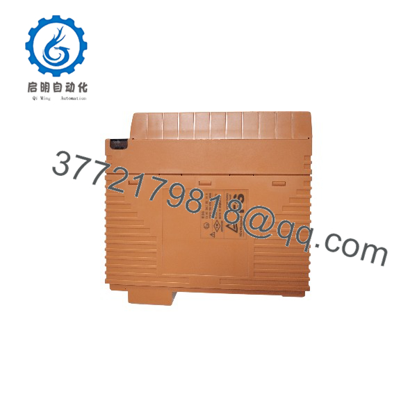
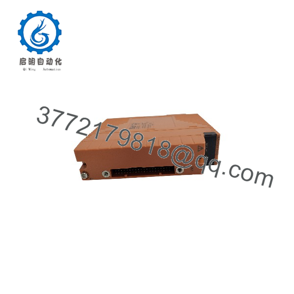
The Yokogawa SAI533-H33 is an analog output module for the ProSafe-RS safety instrumented system, part of the FIO-based SIL3-capable I/O layer that Yokogawa developed for ProSafe-RS. The module drives 8 isolated 4 to 20 mA current output signals from the Safety Control Station to field control devices such as valve positioners, and installs in the safety node unit (SNB10D) or the safety control unit (SSC60, SSC50, SSC10); it can be arranged in a dual-redundant configuration.
The -H suffix specifies HART communication. Through the HART function, the Plant Resource Manager (PRM) manages HART devices connected to the module’s output channels — and on the analog output module specifically, PRM clients can perform Partial Stroke Testing (PST) on HART-supported valve positioners equipped with the PST function, without affecting the safety functions on the Safety Control Station. The trailing digit 3 in the order code specifies the ISA Standard G3 environment rating with a −20 to +70 °C temperature range. Key performance data includes a rated output range of 4 to 20 mA with a guaranteed precision range of 1.25 to 23 mA, an allowable load resistance of 230 to 600 Ω at rated range, ±48 µA accuracy, a 40 ms data update frequency, and support for in-operation PST diagnostics. Each channel can connect one HART device, with a per-channel power supply function for the HART device; the module carries one HART modem and communicates with one HART device at a time.
Key Technical Specifications
| Parameter | Value |
|---|---|
| Product family / type | ProSafe-RS safety instrumented system (SIS) analog output module, FIO-based |
| Order code structure | SAI533-H33: -H = HART communication; trailing 3 = ISA Standard G3, −20 to +70 °C |
| Number of output channels | 8 channels, module isolation |
| Rated output range | 4 to 20 mA |
| Output range / maximum range of guaranteed precision | 1.25 to 23 mA |
| Allowable load resistance at rated range | 230 to 600 Ω |
| Accuracy | ±48 µA |
| Data update frequency | 40 ms |
| Temperature drift | ±16 µA per 10 °C |
| Withstand voltage | 1.5 kV AC between output signal and system for 1 minute (500 V AC when a dedicated signal cable is used) |
| Maximum current consumption | 5 V system: 320 mA; 24 V system: 300 mA |
| HART communication | Available (-H); HART Protocol Revision 5.7, 1200 bps, binary phase-continuous FSK; one HART device per channel; one HART modem per module (concurrent communication with one device) |
| Partial Stroke Test (PST) | Supported; PRM client can execute PST on HART valve positioners with the PST function |
| Redundancy | Module can be made dual redundant |
| External connection styles (module family) | Pressure clamp terminal, MIL cable, dedicated signal cable |
| Weight | Approx. 0.26 kg (pressure clamp terminal block or MIL cable); approx. 0.33 kg (with signal cable interface adapter) |
| Environmental rating | ISA Standard G3; ambient temperature −20 to +70 °C; channel-use restriction above 60 °C ambient applies (see below) |
| Standards context | SAI533 is included in the ProSafe-RS standards-compliant models, with associated accessories SCCC01, STA4D, STA4S, and STK4A |
Engineering Selection Highlights
- HART on the output module enables valve diagnostics in the safety system — the -H function lets PRM clients run Partial Stroke Tests on HART positioners with the PST function, providing in-operation diagnosis of the final element while Yokogawa documents the HART functions as interference-free with the safety functions on the Safety Control Station.
- 8 channels with module isolation, not channel isolation — all outputs share module-level isolation; loop design and fault analysis should treat the isolation boundary accordingly.
- Load resistance window of 230 to 600 Ω at rated range — positioner input impedance plus loop wiring must fall inside this band; low-impedence positioners below 230 Ω or long cable runs pushing past 600 Ω are outside the guaranteed envelope.
- Precision is guaranteed from 1.25 to 23 mA, not just 4 to 20 mA — the wider band supports under-range and over-range signaling; verify trip and alarm thresholds against the ±48 µA accuracy and the 40 ms update period.
- One HART modem per module — although each of the 8 channels can host one HART device with per-channel device power, the module communicates with only one HART device at a time, which governs PRM polling time in multi-device setups.
- Thermal channel restriction — when used above 60 °C ambient, the number of usable output channels is restricted per the ProSafe-RS I/O modules outline document; cabinet cooling design should hold the module below this boundary to keep all 8 channels available.
- Dual redundancy is available — the module can be made dual redundant, and dual-redundant pressure clamp terminal blocks (STA4D type, order option) support the redundant marshalling on the field side.
- Order options shape the terminal hardware — option codes add pressure clamp terminal blocks (STA4S, with or without surge absorber), dual-redundant terminal blocks (STA4D), false-insertion prevention pins (/PRP), and MIL connector covers (/CCC01); these are ordered with the module, not assumed.
SAI533-H33
SAI533-H33
System Compatibility & Integration Requirements
| Item / Dependency | Verified Compatibility or Requirement | Practical Note |
|---|---|---|
| Host system | Yokogawa ProSafe-RS safety instrumented system | Part of the analog I/O module set for ProSafe-RS together with SAI143, SAV144, SAT145, SAR145, SDV144, SDV521 |
| Mounting locations | Safety node unit (SNB10D) or safety control unit (SSC60, SSC50, SSC10) | Module installs in the ProSafe-RS hardware configuration |
| Field devices | 4 to 20 mA control devices such as valve positioners | Load resistance must be 230 to 600 Ω at rated range |
| HART device management | ‘-H supports PRM management of HART devices on output channels; PST on HART positioners with PST function | One HART device per channel; one HART modem per module; HART communication is interference-free with safety functions |
| Redundancy | Module can be made dual redundant | Dual-redundant pressure clamp terminal blocks (STA4D) available as order options |
| Terminal accessories | STA4S / STA4D pressure clamp terminal blocks (with or without surge absorber), STK4A, SCCC01 MIL connector cover, /PRP false-insertion prevention pin | Ordered as option codes with the module |
| Environment | ISA Standard G3, −20 to +70 °C | Number of usable output channels is restricted above 60 °C ambient per the ProSafe-RS I/O modules outline document |
| Standards compliance | SAI533 is among the ProSafe-RS standards-compliant models, including marine standards, with accessories SCCC01, STA4D, STA4S, STK4A | Compliance details are defined in the ProSafe-RS general and standards-compliant model specifications |
Dimensions, Mounting & Connection Notes
| Item | Data |
|---|---|
| Weight | Approx. 0.26 kg for pressure clamp terminal block or MIL cable variants; approx. 0.33 kg with signal cable interface adapter |
| External connection styles | Pressure clamp terminal block, MIL connector cable, or dedicated signal cable via interface adapter |
| Load design values | Allowable load resistance 230 to 600 Ω at rated range; output range 1.25 to 23 mA |
| Insulation test limit | 1.5 kV AC between output signal and system for 1 minute; 500 V AC when a dedicated signal cable is used |
| Power consumption | 320 mA max. on the 5 V system; 300 mA max. on the 24 V system — include in the node power budget |
| Environmental limits | ISA Standard G3; −20 to +70 °C; usable output channel count restricted above 60 °C ambient |
| Ordering options | /A4S00 or /A4S10 pressure clamp terminal block (STA4S-00 / STA4S-10 with surge absorber); /A4D00 or /A4D10 dual-redundant terminal block (STA4D-00 / STA4D-10); /PRP false-insertion prevention pin; /CCC01 MIL connector cover |
Detailed Product Overview
The SAI533 is the current output member of the analog I/O set that Yokogawa built for ProSafe-RS on the FIO hardware base. Where the companion SAI143 acquires 16 channels of transmitter signals, the SAI533 drives 8 channels of 4 to 20 mA outputs toward field control devices, with module-level isolation, and it can be configured in a dual-redundant arrangement within the safety node unit or safety control unit.
The output stage’s electrical envelope is precisely documented and directly shapes loop design. The rated output range is 4 to 20 mA, but the guaranteed precision band extends from 1.25 to 23 mA, giving safety logic room for under-range and over-range signaling while keeping the ±48 µA accuracy figure in force. The allowable load resistance at rated range is 230 to 600 Ω — a window that must accommodate the positioner’s input impedance and the loop wiring resistance together. The data update frequency is 40 ms, with a temperature drift of ±16 µA per 10 °C. Loop insulation testing has a stated limit of 1.5 kV AC between output signal and system, dropping to 500 V AC when a dedicated signal cable is connected — the same cable-dependent distinction that applies to the input modules.
The -H suffix is what distinguishes this variant as an active participant in Yokogawa’s device management environment. The module implements HART communication to Protocol Revision 5.7 at 1200 bps using binary phase-continuous FSK modulation. Each of the 8 channels can host one HART device and provides a power supply function to it, but the module carries a single HART modem and communicates with only one device at a time — a constraint that determines PRM polling behavior when several channels carry HART positioners. Functionally, the HART path lets the Plant Resource Manager manage the connected devices, and on this output module specifically it enables PRM clients to execute Partial Stroke Tests on HART-supported valve positioners equipped with the PST function. Yokogawa documents the HART functions as interference-free with respect to the safety functions on the Safety Control Station: device management traffic runs on a separate path from the safety loop, which is the property that makes online diagnostics acceptable in a safety instrumented system.
The order code’s environment digit (3) fixes the ISA Standard G3 rating with a −20 to +70 °C temperature span. Within that span there is a documented restriction: above 60 °C ambient, the number of output channels a user can operate is restricted, per the ProSafe-RS I/O modules outline document. For cabinet design this creates a practical target — keep the module’s ambient below 60 °C and all 8 channels remain available.
The module’s power draw of 320 mA on the 5 V system and 300 mA on the 24 V system feeds the node-level power budget, and its weight of approximately 0.26 to 0.33 kg depending on the connection style makes multi-module safety node shelves straightforward to plan mechanically. Field-side hardware is ordered with the module through option codes: pressure clamp terminal blocks in standard and surge-absorber versions (STA4S), dual-redundant terminal blocks (STA4D) for redundant marshalling, false-insertion prevention pins, and MIL connector covers. For procurement, the key verification points are the suffix digits against the installed connection style, the option codes against the plant’s terminal hardware, and — where PST is part of the design intent — confirmation that the connected positioners support the HART PST function.
Applications & System Role
In a ProSafe-RS architecture, the SAI533-H33 is the safety-side analog actuation point: it converts the Safety Control Station’s commanded positions or setpoints into 4 to 20 mA signals for field control devices — most characteristically valve positioners in shutdown, depressurization, and other safety-related actuation loops. The module belongs to the SIL3-capable FIO-based I/O family developed for ProSafe-RS, alongside the SAI143 current input, SAV144 voltage input, SAT145 thermocouple/mV input, SAR145 RTD input, and SDV digital I/O modules.
Fit scenarios that follow from the verified capability profile:
- Safety loops that modulate or command an analog final element, where the safety logic must drive a 4 to 20 mA output rather than a discrete trip signal.
- Valve installations supervised by Yokogawa PRM, where the -H HART function supports positioner configuration, diagnostics, and in-operation Partial Stroke Testing without interfering with the safety function.
- Redundant safety I/O designs, since the module supports dual redundancy and dual-redundant field terminal hardware is available as an ordering option.
- Process areas with demanding environments, covered by the ISA G3 rating from −20 to +70 °C, subject to the documented channel restriction above 60 °C.
FAQ
What is the Yokogawa SAI533-H33?
It is an 8-channel, 4 to 20 mA analog output module for the ProSafe-RS safety instrumented system, with HART communication and an ISA G3 environment rating.
What do the suffix codes mean?
-H specifies HART communication; the trailing digit 3 specifies the ISA Standard G3 environmental rating with a −20 to +70 °C temperature range.
Where is the module installed?
In the ProSafe-RS safety node unit (SNB10D) or safety control unit (SSC60, SSC50, or SSC10); it can be made dual redundant.
What are its output specifications?
Rated output range 4 to 20 mA, guaranteed precision range 1.25 to 23 mA, accuracy ±48 µA, allowable load resistance 230 to 600 Ω at rated range, and a 40 ms data update frequency.
What does the HART function provide?
It allows the Plant Resource Manager to manage HART devices on the output channels, including Partial Stroke Testing of HART valve positioners with the PST function, without impacting the safety functions on the Safety Control Station.
How many HART devices can be connected?
One HART device per channel, with per-channel power supply to the device; the module has one HART modem and communicates with one device at a time.
What installation limits apply?
ISA Standard G3 environment from −20 to +70 °C, with the usable output channel count restricted above 60 °C ambient; insulation testing is limited to 1.5 kV AC (500 V AC with a dedicated signal cable).
What terminal hardware options exist?
Pressure clamp terminal blocks (STA4S, with or without surge absorber), dual-redundant terminal blocks (STA4D), a false-insertion prevention pin (/PRP), and a MIL connector cover (/CCC01), ordered as option codes with the module.