WhatsApp: +86 16626708626
 Email:
 Phone: +86 16626708626
Description
Core Product Summary (Brand / Model / Key Attributes)
The Yokogawa UT2800-1HB is a panel-mounted digital indicating controller engineered for precise temperature and industrial process regulation. Functioning within heat treatment systems, industrial ovens, furnaces, environmental test chambers, and process fluid lines, the unit combines real-time Process Variable (PV) indication with automatic closed-loop PID control and monitoring capabilities.
The model code designation UT2800-1HB identifies a specific hardware configuration within the Yokogawa UT2800 series controller family. It features a universal analog input capable of interfacing directly with thermocouples, Resistance Temperature Detectors (RTDs), DC current (4–20 mA), and DC voltage (1–5 V) instrumentation. Equipped with dual front-panel LED displays for clear PV and Setpoint (SV) tracking, auto-tuning PID control logic, multi-channel alarm outputs, and high noise immunity, the unit delivers stable loop control in compact panel layouts.
Key Technical Specifications
| Parameter | Specification |
| Model Number | UT2800-1HB (also designated UT2800-1/HB) |
| Manufacturer | Yokogawa Electric |
| Product Family | UT2800 Series |
| Product Type | Digital Indicating Process Controller |
| Input Type | Universal Input (Thermocouple, RTD, 4–20 mA DC, 1–5 V DC) |
| Control Algorithms | PID control with Auto-Tuning, ON/OFF control |
| Display System | Dual digital LED display for Process Variable (PV) and Setpoint (SV) |
| Control Output Options | Relay contact, voltage pulse, or analog current output |
| Alarm Functions | Multi-channel alarm relay outputs |
| Power Supply | 100–240 V AC (50/60 Hz) |
| Front Protection | IP65 dust and water-resistant front panel |
| Mounting Format | Standard panel mount |
Detailed Product Overview
The Yokogawa UT2800-1HB digital indicating controller provides localized loop control and process monitoring for automated industrial processes. Engineered to replace manual tuning or basic analog controllers, the UT2800-1HB uses digital processing algorithms to maintain process variables at predefined target setpoints while suppressing external process disturbances.
The controller’s universal input hardware allows field configuration for a wide variety of sensor types. Engineers can configure the input stage to accept standard industrial thermocouples (such as Type K, J, or T), 100-ohm platinum RTDs (Pt100), or linear DC instrumentation signals (4–20 mA or 1–5 V). Front-panel dual LED displays continuously present both the measured process value and the target setpoint, giving machine operators clear status visibility.
Integrated auto-tuning functionality simplifies loop startup by calculating optimal proportional, integral, and derivative (PID) parameters based on observed process dynamics. Built-in alarm relays provide configurable high, low, or deviation alarm trip points to protect equipment and process media from out-of-spec thermal conditions. With high electrical noise immunity and an IP65-rated front faceplate, the UT2800-1HB maintains reliable control in harsh factory environments.
Engineering Selection Highlights
- Universal Input Hardware → Accepts thermocouple, RTD, DC voltage, and DC current signals, reducing spare parts inventory across different machine sensor configurations.
- Built-in Auto-Tuning Logic → Automatically determines baseline PID constants during system startup, reducing commissioning time on complex thermal loops.
- Dual PV/SV Display Interface → Provides simultaneous, highly visible digital displays for real-time process monitoring and setpoint verification.
- Configurable Alarm Relays → Multi-channel alarm outputs allow direct interlock wiring to external annunciators, safety shutoff valves, or PLC discrete inputs.
- Rugged Panel Enclosure → Features an IP65-rated front panel to resist moisture and industrial airborne dust when mounted in control cabinet cutouts.
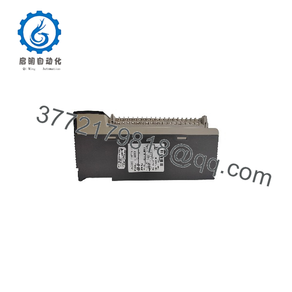
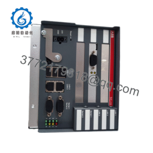
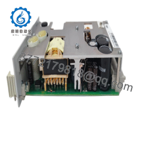
UT2800-1HB
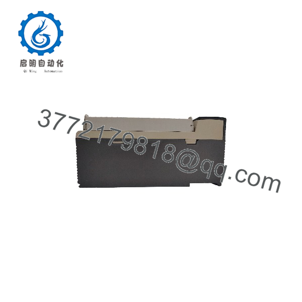
UT2800-1HB
System Compatibility & Integration Requirements
| Item / Dependency | Verified Compatibility or Requirement | Practical Note |
| Primary Input Sensor | Thermocouples, RTDs, 4–20 mA, or 1–5 V transmitters | Sensor selection and input range must be matched in internal parameter settings. |
| Panel Cutout | Standard panel mount cutout | Installs into control cabinet door cutouts using side-mounting retainers. |
| Operating Power | 100–240 V AC line power | Requires external AC line fusing and a dedicated disconnect switch per electrical safety codes. |
| Output Actuation | Heaters, solid-state relays (SSRs), control valves | Control output signal type (relay, voltage pulse, current) must match final control element requirements. |
Dimensions, Mounting & Connection Notes
- Mounting: Standard flush panel mounting format. Insert unit into the front panel cutout and secure using the provided side-mounting brackets.
- Front Panel Rating: IP65 ingress protection when properly installed against a smooth, flat enclosure surface with a intact rubber gasket.
- Field Wiring: Rear screw terminal block for sensor inputs, power supply lines, control outputs, and alarm wiring.
- Wiring Separation: Route low-voltage sensor input wiring in separate conduits away from AC power lines, heavy motor leads, and switching inductive loads to prevent signal interference.
FAQ
What is the Yokogawa UT2800-1HB?
The UT2800-1HB is a panel-mounted digital indicating controller manufactured by Yokogawa for precision temperature and process loop control.
What types of sensor inputs are compatible with the UT2800-1HB?
It features a universal input stage compatible with thermocouples, RTDs (Pt100), 4–20 mA current signals, and 1–5 V DC voltage signals.
What control modes does the UT2800-1HB support?
The controller supports automatic PID control with built-in auto-tuning as well as basic ON/OFF control modes.
What power supply voltage is required for operation?
The unit operates on a standard universal power supply range of 100–240 V AC (50/60 Hz).
What is the front panel ingress protection rating for this model?
The front faceplate is rated IP65 for protection against dust and water ingress when panel-mounted.
Verification & Troubleshooting Notes
High Voltage Electrical Hazard
Isolate all external AC power sources before accessing the rear screw terminals or wiring field connections on the UT2800-1HB controller. Electric shock can cause severe injury or equipment damage.
1.Verify Main Power Supply Voltage:Power check.
Apply digital multimeter probes to the rear power terminals to confirm line voltage (100–240 V AC) is present.
Verification: The front panel LED display illuminates and completes its initial self-test diagnostic cycle upon power application.
2.Inspect Input Wiring and Parameter Configuration:Sensor check.
Check sensor lead connections on the rear input terminals and verify that internal input parameter settings match the connected sensor type (e.g., Type K thermocouple vs Pt100 RTD).
Verification: The PV display indicates a stable process value corresponding to ambient or process conditions rather than an overrange/underrange error message.
3.Test Control and Alarm Outputs:Output verification.
Manually adjust the setpoint (SV) above and below the current process value (PV) to observe output relay state changes.
Verification: Output indicators illuminate on the front panel, and connected field actuators (relays, valves, or SSRs) trigger accordingly.