
 WhatsApp: +86 16626708626
 Email:
  Phone: +86 16626708626
Description
Key Technical Specifications
- Measurement Principle: Fizeau-type laser interferometry
- Primary Application: Quantitative inspection of aspheric optical surfaces
- Measured Characteristics: Surface figure error, surface irregularity, radius of curvature, and form deviation
- Optical Component Types: Aspheric, spherical, flat, cylindrical, and precision optical components, subject to installed optics and software configuration
- Light Source: Stabilized laser source; exact laser wavelength must be verified by system serial number and installed configuration
- Reference Optics: Configurable interferometric reference optics and compensating optics for aspheric measurements
- Measurement Method: Noncontact optical measurement
- Typical Use Environment: Optical manufacturing, incoming inspection, research laboratories, precision machining, and optical assembly verification
- System Configuration: May include interferometer head, computer/controller, application software, mounting hardware, reference optics, and compensator optics
- Communication/Software: Configuration-dependent; verify installed ZYGO software version, PC interface, operating-system compatibility, and software-license status before purchase
- Power Requirement: Verify from the system nameplate and installed controller; do not assume standard industrial 24 V DC operation
- Condition Note: A complete functional check requires the matching optical head, reference optics, compensator, computer, software, and calibrated test artifact
The ZYGO 4205 is identified in reseller listings as a Verifire Asphere system used for high-precision interferometric inspection of aspheric optical components. ZYGO’s product portfolio includes optical metrology systems and related optical measurement technologies.
Product Introduction
The ZYGO 4205 Verifire Asphere is a precision laser interferometer system for noncontact measurement of aspheric optical surfaces. Optical manufacturers and metrology labs use it to evaluate surface figure, irregularity, curvature, and form error before an optic moves into coating, assembly, or final acceptance.
The value is in configuration-specific asphere measurement capability, not merely the 4205 label. Before ordering, verify the included interferometer head, transmission flat or reference optics, compensator optics, software license, PC/controller, wavelength, and calibration status. A base system without the correct compensator may not test your part.
Troubleshooting Quick Reference
| Symptom | Possible Cause | Relevance to this Part | Quick Check Method | Recommendation |
|---|---|---|---|---|
| No power or no controller startup | Failed AC supply, disconnected power cord, blown fuse, failed PC power supply | ❌ Low to medium | Verify mains voltage at the input, inspect the external fuse, and confirm the controller/PC power supply outputs its rated DC rails | Check power infrastructure before condemning the 4205 optical system |
| Interferogram does not appear | Laser source not enabled, shutter closed, disconnected optical head, failed camera connection | ✅ High | Confirm laser-enable status, inspect interconnect cables, verify camera/frame-grabber recognition, and check for visible alignment output only through approved safety procedures | Inspect cables and configuration first; replace the affected optical head or controller only after isolation testing |
| Fringe image is dim or unstable | Contaminated optics, vibration, air turbulence, laser warm-up issue, incorrect exposure settings | ✅ Medium | Clean optics using approved optical-cleaning procedures, allow full warm-up, stabilize the bench, and compare image intensity with a known-good reference setup | Do not immediately replace the system; environmental instability causes many false failures |
| Software cannot communicate with hardware | Incorrect interface driver, USB/PCI/frame-grabber fault, unsupported operating system, missing license | ✅ High | Check Device Manager or interface diagnostics, confirm installed software version, review license status, and test with the original controller if available | Preserve the original hard drive or make an image before changing drivers or software |
| Measurements show repeatability errors | Vibration, thermal drift, loose mounting, damaged reference optic, wrong compensation file | ✅ High | Run repeated measurements on a calibrated reference artifact, inspect mounting fasteners, verify compensator identification, and monitor room temperature | Confirm environmental stability and optics configuration before sending the system for repair |
| Measured surface map looks distorted | Wrong transmission element, incorrect compensator, alignment error, tilted test optic | ✅ High | Verify the part setup against the approved test procedure, identify the installed compensator, and perform alignment using a known-good artifact | Do not treat distorted data as an electronics failure; setup errors are more common |
| System identifies the hardware but cannot complete acquisition | Frame-grabber fault, camera fault, controller resource issue, software version mismatch | ✅ Medium to high | Test acquisition using the original software configuration, inspect internal interface cards, and compare against a documented known-good configuration | Document software, driver, and hardware revisions before replacing anything |
| Surface data suddenly shifts after moving the system | Optical head alignment changed, mount loosened, compensator moved, reference surface contaminated | ✅ High | Check mechanical datum points, inspect mounting hardware, re-run alignment, and repeat the test on a stable reference optic | Re-align and validate against a reference artifact; shipping or bench movement can affect measurement setup |
| Noisy data only on one production part | Part contamination, coating issue, surface scatter, incorrect part handling | ❌ Low | Inspect the test optic under controlled illumination and compare the result with another known-good part | Investigate the optic and test setup before assuming the 4205 has failed |
❗ Do not wire, service, or disassemble the laser head from memory. This is not a typical PLC module: optical alignment, installed reference optics, compensation files, software licensing, and environmental control all affect whether the system produces valid measurement data.
If you are stuck, send technical support clear photos of the system nameplates, installed optical head and compensator labels, controller ports, software version screen, error messages, and a sample interferogram or measurement log.
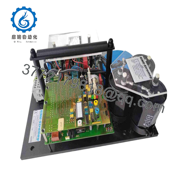
4205
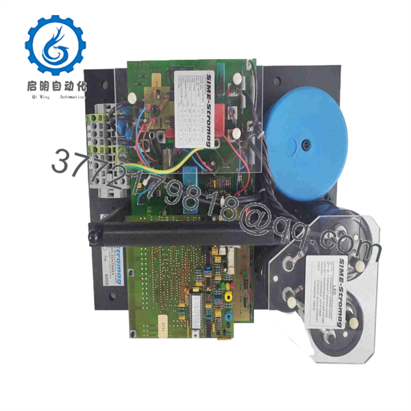
4205
Frequently Asked Questions
Is the ZYGO 4205 a standalone instrument?
Usually, no. A usable 4205 configuration may include the interferometer head, reference optics, asphere compensator optics, mounting hardware, controller or PC, interface cards, ZYGO measurement software, and a valid software license. Confirm exactly what is included in the quotation. A system that powers on but lacks the correct compensator may not be usable for your aspheric part.
Can the ZYGO 4205 measure any aspheric optic?
No. That is the trap with used interferometric equipment. Asphere measurement depends on the optical design, installed compensator or null optics, wavelength, aperture, test geometry, and software configuration. Provide the optic drawing, prescription, clear aperture, nominal radius, conic constant, wavelength requirements, and existing compensator part number before purchase.
Is ZYGO 4205 obsolete?
The 4205 is generally encountered on the secondary and surplus-equipment market rather than as a current standard catalog item. That means availability depends on complete system configuration, cosmetic condition, included accessories, calibration history, and the availability of original software and optics. Limited stock is normal for this class of legacy metrology equipment.
Can I use my existing ZYGO software and controller with this unit?
Maybe, but do not assume it. You need to verify software version, controller hardware, camera or frame-grabber interface, driver compatibility, operating system, installed license, and the optical head’s supported configuration. I have seen a technician swap metrology hardware and lose two days to a communication fault caused by an old interface driver paired with a newer PC. Record every revision before removing the original hardware.
Does the system retain measurement setups during a replacement?
The optical hardware itself does not guarantee retention of measurement recipes, compensator files, calibration data, alignment settings, and test-part programs. Back up the original PC, copy all ZYGO application directories where permitted, record installed software versions, photograph all optical and mechanical setup positions, and retain files associated with the existing compensator. Treat the old controller drive as a critical spare.
Can I hot-swap the optical head, camera, or interface hardware?
No. Shut down the system, isolate power, follow the manufacturer’s service procedure, and use ESD controls before touching electronics. It is the most common rookie mistake, but it happens constantly: take photos of every cable, optical mount, DIP switch, and interface-card position before removal. Seriously. A swapped cable or incorrect interface-card slot can turn a simple replacement into a long alignment and driver-recovery job.
Why is a New Surplus ZYGO 4205 less expensive than factory-supplied equipment?
New Surplus equipment is typically unused inventory from an OEM, integrator, laboratory closure, canceled project, or inventory liquidation. The lower price usually reflects age, limited factory support, possible absence of current calibration certification, and configuration-specific accessories rather than automatic defects. Confirm the exact included hardware, test documentation, packaging condition, software/license status, and warranty terms before issuing a purchase order.
What testing should a supplier perform before shipment?
At minimum, require documented inbound inspection, serial-number photos, visual inspection for corrosion or rework, a power-on test, laser/interferogram acquisition check, camera and software communication check, repeated measurement using a known reference artifact, and a final photo set. For a complete configured system, request a live test video and measurement report. Test videos and photos should be available upon request.



