
 WhatsApp: +86 16626708626
 Email:
  Phone: +86 16626708626
Description
Key Technical Specifications
| Parameter | Value |
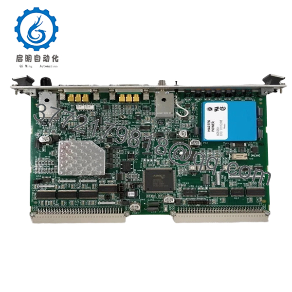
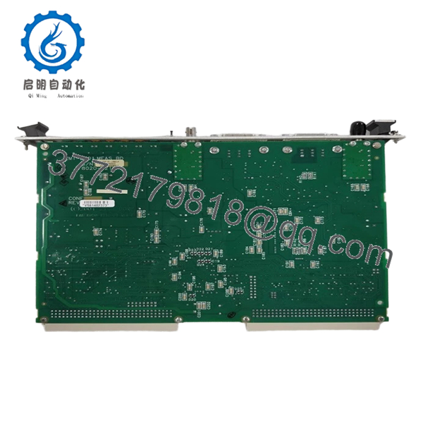
| Board Type | Single-Axis 6U VME Bus |
| Input Signal | Reference/Measurement Fiber Optic |
| Position Resolution | 36-bit (2’s complement) |
| Velocity Format | 32-bit (2’s complement) |
| Power Requirement | +5V DC ± 5% @ 3.5A |
| VME Compliance | Revision C.1 (A16/A24 Addressing) |
| Synchronization | Clock In / Clock Out (Master/Slave capable) |
| Operating Temp | Standard Industrial Range |
| Form Factor | 6U VME Eurocard |
Product Introduction & Supply Chain Strategy
The Zygo ZMI-2001 is a foundational component in high-precision displacement measuring interferometer (DMI) systems. It processes raw optical feedback from laser sources to provide sub-nanometer position data, serving as the “brain” for stage control in semiconductor steppers, scanners, and wafer inspection equipment. Its architecture allows for precise synchronization across multiple axes in a VME chassis.
Procuring the ZMI-2001 as “New Surplus” is a mission-critical strategy for facilities running legacy metrology tools. Because these cards reside in harsh, vibration-prone environments, their internal components are subject to thermal cycling fatigue. We supply only New Surplus units, which eliminates the hidden risks associated with “used” boards—such as oxidized VME pins or intermittent gate array failures—ensuring your tool avoids expensive downtime during critical production runs.
Installation & Configuration Guide
Stage 1: Pre-Installation (Prep & Safety)
Power down the VME chassis and disconnect the main supply. Use an anti-static wrist strap connected to the chassis ground. Ensure the ZMI-2001 slot is free of debris. Inspect the P1/P2 connector pins on the backplane for any bent pins before insertion.
Stage 2: Removal
Depress the ejector handles on the existing card to disengage it from the backplane. Slide the card out along the card guide rails. Do not force the board if it catches; check the rails and adjacent cards for alignment.
Stage 3: Installation (Clone & Seat)
Align the new ZMI-2001 with the guide rails. Slide it in until the connectors engage, then use the ejector handles to lock it firmly into the backplane. Ensure the fiber optic inputs for the reference and measurement beams are securely connected and free of dust contamination.
Stage 4: Power-On & Testing
Apply power and verify that the board’s status LEDs indicate a successful power-on self-test (POST). Use the VME bus interface software to confirm the board address is recognized and that the measurement signal is locking on (Reference/Measure signal LEDs should be active).

- ZMI-2001
- ZMI-2001
Firmware/Software Versions & Upgrade Notes
- VME Addressing: Ensure the jumper settings on the new board exactly match the old board’s memory map configuration (A16 or A24 addressing) to prevent bus conflicts.
- Compatibility: This board is designed for the ZMI 2000 series ecosystem. Do not attempt to swap logic firmware; the ZMI-2001 utilizes hardware-based processing logic.
- Integration: If you are expanding an axis count, ensure the chassis clock master is correctly assigned so that all synchronized ZMI boards share a common time base (essential for nanometer-level overlay accuracy).
Frequently Asked Questions (FAQ)
How can I be sure this isn’t a “pull” from a scrapped machine?
We define “New Surplus” as inventory that has never been installed or used in a production environment. Unlike “refurbished” or “pulled” units, our ZMI-2001 boards have pristine edge connectors, clean anti-static packaging, and no evidence of thermal stress on the ICs.
Why is New Surplus better than a refurbished Zygo board?
Refurbished boards often have capacitors nearing the end of their service life or hidden trace damage from previous handling. In a metrology application, a single “glitch” due to a degraded component can cause a wafer mis-alignment, leading to thousands of dollars in scrap. New Surplus eliminates these variables.
Can I use the ZMI-2001 with ZMI-2002 boards in the same chassis?
Yes, the ZMI 2000 series boards are designed to be mixed within the same VME backplane. Ensure that your software drivers and synchronization clock settings are configured to account for the single-axis (2001) vs. dual-axis (2002) board types.
Do you provide calibration reports with these boards?
These are digital measurement boards. They do not require “calibration” in the traditional sense, but they are tested for signal integrity and VME bus communication to ensure they function exactly to the original OEM specification upon arrival.
What should I do if the “Reference” signal LED is flashing?
A flashing reference signal usually indicates a loss of lock or signal instability. First, verify that the fiber optic cables are clean and fully seated. If the issue persists, ensure your ZMI laser source is providing the correct heterodyne frequency to the board.


