
 WhatsApp: +86 16626708626
 Email:
  Phone: +86 16626708626
Description
3. Key Technical Specifications
| Parameter | Value |
| ABB Part Number | 3BHB021400R0002 |
| ABB Model Designation | 5SHY4045L0004 (sub-assembly code: GVC736) |
| Component Architecture | Asymmetric Integrated Gate-Commutated Thyristor (IGCT) |
| Peak Off-State Voltage (V_{DRM}) | 4500 V |
| Turn-Off Current (I_{TGQM}) | Up to 4000 A (Snubberless) |
| Silicon Wafer Diameter | 91 mm |
| Clamping / Mounting Force | Nominal 40 kN (Kilonewtons) |
| Gate Unit Operating Power | 24 VDC auxiliary control voltage |
| Command Signaling | Fiber-optic transmitter/receiver ports |
| Cooling Method | Double-sided liquid or forced-air heatsink clamping |
| Weight | Approximately 3.3 kg (7.3 lbs) |
4. Product Introduction & Application Strategy
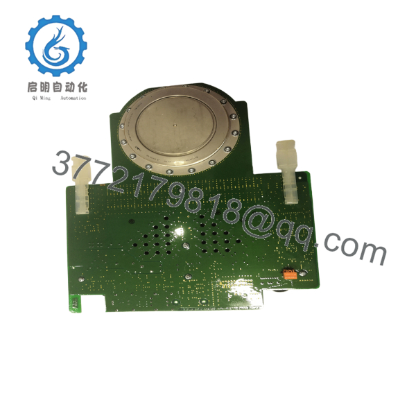
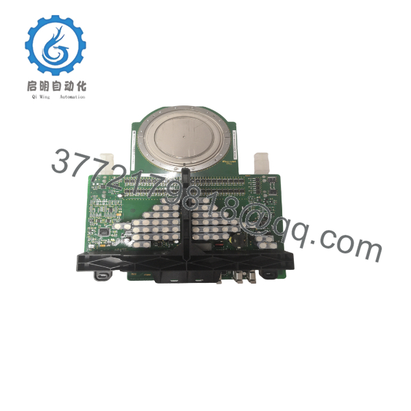
The ABB 3BHB021400R0002 is a high-power Asymmetric Integrated Gate-Commutated Thyristor (IGCT) engineered specifically for demanding, high-voltage industrial applications. It is most commonly found in ABB’s ACS6000 medium voltage drives, railway traction converters, marine propulsion units, and grid stability systems (like STATCOM or Flexible AC Transmission Systems).
By integrating the gate driver card directly onto the physical thyristor disc housing, this device minimizes lead inductance. This allows the IGCT to combine the low conduction losses of a classic thyristor with the fast, snubberless turn-off capabilities of a modern transistor (IGBT).
In multi-megawatt systems, the 3BHB021400R0002 handles intense thermal cycling and high electrical loads daily. Sourcing this module as a certified New Surplus unit protects your equipment from the risks associated with pulled or used parts. Refurbished semiconductors can harbor hidden silicon degradation, micro-fractures in the casing, or aging electrolytic capacitors on the integrated gate board that are highly prone to sudden failure under load. Keeping a factory-original, zero-hour surplus spare on-site ensures your maintenance crew can swap out failed components immediately, restoring your power systems safely.

- 3BHB021400R0002
- 3BHB021400R0002
5. Installation & Mechanical Clamping Rules
Stage 1: Safety & Isolation
Perform full lock-out/tag-out (LOTO) procedures on all AC and DC feed lines. Ensure the drive’s main DC capacitor banks are completely discharged. Verify that the bus voltage is at 0V using a certified high-voltage meter. Wear a grounded ESD wrist strap when handling the IGCT’s fiber-optic ports and gate terminal inputs.
Stage 2: Mechanical Setup
Remove the auxiliary 24 VDC power plug and fiber-optic cables from the integrated gate driver unit. Release the clamp pressure on the heatsink stack and slide the damaged module out. Thoroughly clean the contact surfaces of both the new IGCT disc and the heatsink plates using an approved solvent. Apply a very thin, uniform layer of high-conductivity thermal joint compound to the contact faces.
Stage 3: Precise Mounting Force Application
Slide the new 3BHB021400R0002 into the stack, checking that its orientation matches the surrounding phases. Use a calibrated hydraulic or spring tension clamp to apply the required 40 kN mounting force evenly across the presspack:
- Under-tightening increases thermal resistance, leading to localized hot spots and thermal runaway.
- Over-tightening can crush the delicate internal silicon wafer, causing immediate destruction upon startup.
Stage 4: Control Wiring & Startup
Reconnect the fiber-optic communication lines and the auxiliary 24 VDC power harness. Energize the low-voltage auxiliary control circuits first to confirm that the integrated gate driver board boots correctly, displays a “Ready” state, and passes diagnostic self-checks before applying high voltage.
6. Frequently Asked Questions (FAQ)
What does “Asymmetric” mean in the context of this IGCT?
An asymmetric IGCT like the 3BHB021400R0002 is optimized to provide high reverse-blocking voltage capacity in only one direction. This design allows for significantly lower forward conduction losses and faster switching speeds compared to symmetric IGCTs, making it ideal for voltage-source inverters (VSIs) that use a free-wheeling diode in parallel.
Is the gate driver board included with this part number?
Yes. The 3BHB021400R0002 is an Integrated Gate-Commutated Thyristor. The gate driver circuit board is permanently attached to the housing as a single factory-calibrated assembly to minimize lead inductance and ensure highly reliable switching performance.
Is this unit a standard refurbished module?
No. This is a Brand New Surplus unit. It has not been used or salvaged from decommissioned equipment, and has not undergone third-party electronic repairs. The device is shipped in factory-grade protective packaging, featuring clean, unmarred copper contact faces and pristine fiber-optic ports.
What warranty terms apply to this high-voltage component?
Every New Surplus 3BHB021400R0002 module is backed by our comprehensive 1-year operational warranty from your date of purchase. If a material or component defect arises during this window under normal operating parameters, we will facilitate an immediate replacement or repair.



