
 WhatsApp: +86 16626708626
 Email:
  Phone: +86 16626708626
Description
Key Technical Specifications
| Parameter | Value |
| Manufacturer | ABB |
| Model Number (MPN) | 5SHY3545L0009 |
| Associated Part Number | 3BHB013085R0001 |
| Component Type | Integrated Gate Commutated Thyristor (IGCT) |
| Repetitive Peak Off-State Voltage (V_{DRM}) | 4500 V |
| Maximum Turn-Off Current (I_{TGQM}) | 3500 A |
| Maximum Junction Temperature (T_{vj}) | 125 °C |
| Integrated Components | GCT Semiconductor Element, Low-Inductance Gate Unit |
| Control Interface | Fiber Optic Transmitter/Receiver Pairs |
| Cooling Profile | Press-pack double-sided thermal dissipation |
| Net Weight | 2.80 kg (6.17 lbs) |
| Dimensions (W x H x D) | 140 mm x 140 mm x 105 mm |
Product Introduction & Supply Chain Strategy
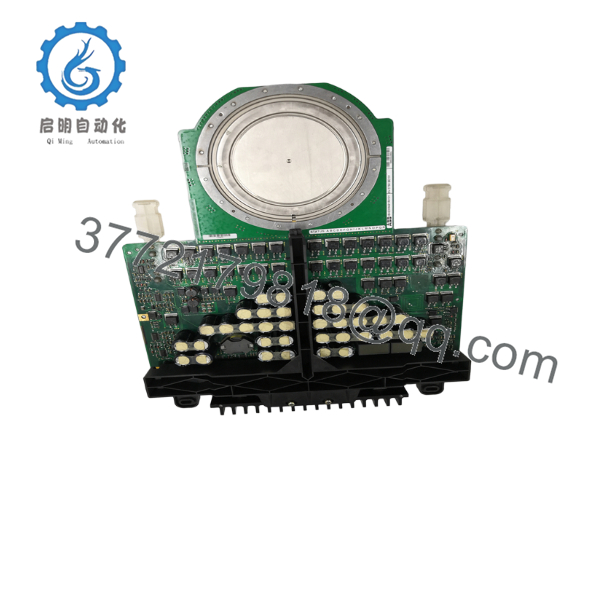
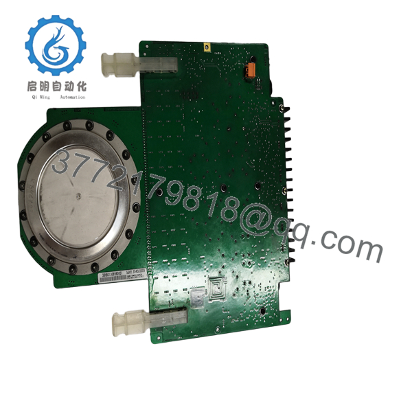
The ABB 5SHY3545L0009 (3BHB013085R0001) is a high-capacity Integrated Gate Commutated Thyristor (IGCT) semiconductor designed for critical power conversion stages in medium-voltage variable frequency drives, static var compensators, and co-generation systems. This press-pack component integrates a high-voltage thyristor wafer with an optimized, low-inductance gate driver unit, enabling fast turn-off performance that eliminates the need for passive snubber sub-assemblies. The resulting topology provides highly efficient switching behavior and reliable thermal performance under demanding, full-load operations.
From a procurement and lifecycle management perspective, this IGCT module is classified as a critical “Class A” engineering asset. Because replacement lead times from factory production runs can stretch into several months, maintaining a New Surplus unit on-site serves as an essential buffer stock insurance policy against catastrophic downtime costs. Choosing our factory-sealed units mitigates the operational hazards common to refurbished semiconductors—such as thermal aging and cracked silicon substrates—ensuring long-term asset availability and lowering the Total Cost of Ownership (TCO) across your high-power infrastructure.
Condition Iron Law Declaration: This product is a Brand New Surplus unit. It is not used, not pulled from a decommissioned plant, and not refurbished. All modules undergo rigorous quality verification to ensure OEM-level reliability.

- 5SHY3545L0009 3BHB013085R0001
- 5SHY3545L0009 3BHB013085R0001
Installation & Configuration Guide
Stage 1: Pre-Installation (Prep & Safety)
- Execute a comprehensive lock-out/tag-out (LOTO) sequence on the three-phase AC mains and the high-voltage DC link assembly feeding the converter cabinet.
- Confirm using a certified high-voltage differential meter that the capacitor banks have fully discharged to 0 V before removing safety access panels.
- Don an ESD-safe protective jacket and ground strap. Clean the press-pack mounting area, and verify your calibrated torque wrench is ready for installation.
Stage 2: Removal
- Disconnect the low-voltage auxiliary power supply plug and the delicate fiber optic control connections from the integrated gate driver unit enclosure.
- Gradually back off the compression force on the primary heavy-duty press-pack clamping fixture to release tension on the semiconductor wafer.
- Keep the assembly completely parallel while sliding the old 2.80 kg module out from the copper heatsink profiles. Avoid dragging the contact faces to protect the surface plating.
Stage 3: Installation (Clone & Seat)
- Clean the adjacent copper busbar faces using a lint-free pad and a high-purity volatile solvent to strip off old thermal compounds and surface oxides.
- Apply an ultra-thin, completely uniform film of premium conductive thermal paste across both contact faces of the new 5SHY3545L0009 module.
- Carefully slide the module into the center of the heatsink assembly, checking that it sits perfectly flat and parallel to eliminate mechanical hot spots.
- Tighten the press-pack clamp progressively with a calibrated torque wrench, applying the precise clamping force required by the cabinet specification to guarantee proper electrical and thermal connections.
Stage 4: Power-On & Testing
- Reconnect the fiber optic communication cables and the auxiliary gate driver low-voltage power connections.
- Clear the LOTO protocols and energize only the low-voltage control circuits. Verify the localized gate unit passes its power-on self-test and displays a steady operational status LED without throwing any communication errors.
- Apply primary high-voltage power to the system. Monitor the operational temperatures across the semiconductor stack using a thermal camera during initial load adjustments to confirm balanced thermal dissipation.
Firmware/Software Versions & Upgrade Notes
The 5SHY3545L0009 functions as a hardware-driven power semiconductor component whose primary operating metrics are defined by the layout of its physical gate unit and thyristor wafer. It does not contain an independent programmable application software layer or logic firmware memory.
Even so, you must verify that the engineering revision code printed on the 3BHB013085R0001 label matches the drive control configuration specified by the system processor (such as an ABB AC 800PEC controller). Variations in internal gate driver component revisions can modify switching delay variables slightly. Never mix different revision variants inside the same phase leg configuration, because asymmetric switching speeds can introduce uneven current balancing, causing immediate overcurrent protection trips.
Frequently Asked Questions (FAQ)
What makes this New Surplus 5SHY3545L0009 unit superior to a refurbished option?
Our New Surplus 5SHY3545L0009 modules are pristine, authentic units that have never been put into active high-voltage rotation or subjected to cyclic thermal stress. Refurbished high-power semiconductors carry serious operational risks: their inner silicon structure can develop micro-fractures from prior overvoltage exposure that are invisible to basic visual inspections. Using a refurbished module in heavy industrial applications creates an unneeded gamble that can result in unexpected breakdown costs that far outweigh the original purchase savings.
Are these modules tested before being added to inventory?
Yes. Every 5SHY3545L0009 module undergoes comprehensive incoming traceability inspection and functional testing, including gate unit insulation checks, fiber-optic link verification, and dynamic gating simulation. This detailed process guarantees that the component matches all factory operating parameters out of the box.
Do I need to modify the main system software configuration when installing this new card?
No software adjustments or programming downloads are needed. The 5SHY3545L0009 triggers its internal gating actions based entirely on the high-speed fiber-optic pulses provided by the master drive computer. As long as your physical part numbers and assembly layout configurations align, the drive system will interact with the new module immediately.
Why are fiber optic connections utilized on the gate driver unit?
High-power megawatt applications produce extreme amounts of electromagnetic interference (EMI) during standard operation. Fiber optic lines offer absolute galvanic isolation between the lethal high-voltage paths running through the thyristor disc and the low-voltage control hardware, ensuring zero signal corruption or accidental triggering risks.
What is the recommended long-term storage protocol for this module?
The module should be kept in a climate-controlled, dry indoor environment inside its original sealed anti-static bag. Because the module doesn’t rely on wet electrolytic components that degrade over time, its shelf life exceeds 10 years, making it an excellent long-term option for your critical on-site buffer stock.



