
 WhatsApp: +86 16626708626
 Email:
  Phone: +86 16626708626
Description
3. Key Technical Specifications
| Parameter | Value |
|---|---|
| Manufacturer | ABB |
| Model | DDC779CE102 |
| Product ID | 3BHE027859R0102 |
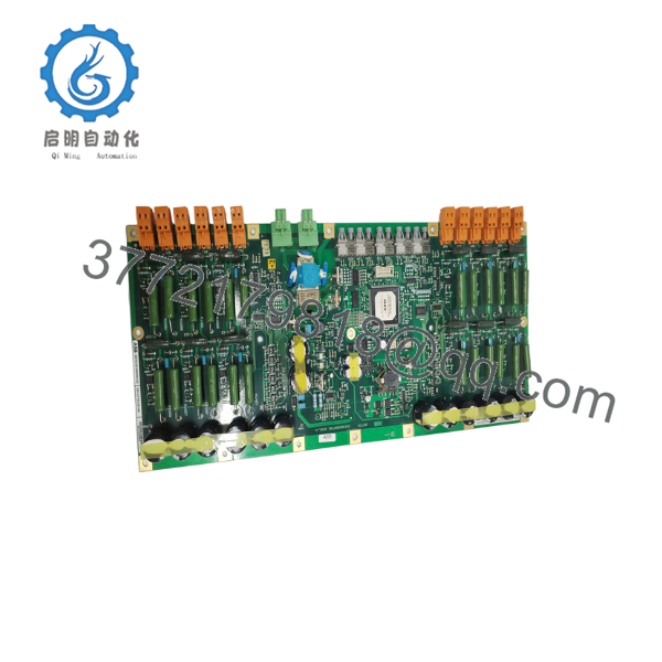
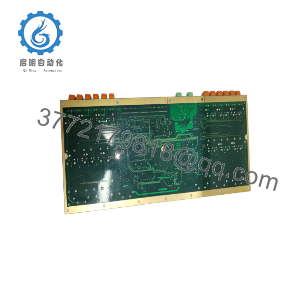
| Product Type | PUB/PFF Interface Board (MC Interface Board) |
| Function | Control and power interface communication |
| Installation | ABB drive control cabinet |
| Communication | PUB/PFF internal communication interface |
| Cooling | Natural cabinet cooling |
| Diagnostics | Integrated status and diagnostic support |
| Dimensions | 449.6 × 185.5 × 50 mm |
| Weight | Approximately 1.3 kg |
| Country of Manufacture | Switzerland |
ABB does not publicly publish a comprehensive electrical specification for this board. Verify firmware compatibility, hardware revision, and drive type against the OEM documentation before replacement.
4. Product Introduction
The ABB DDC779CE102 (3BHE027859R0102) is a PUB/PFF interface board used within selected ABB industrial drive and power converter systems. It provides the communication interface between the machine control electronics and power control assemblies, supporting reliable data exchange inside the drive architecture.
In field service, this board is typically replaced during corrective maintenance after communication faults or hardware failures. Before installation, verify the complete part number, hardware revision, and associated drive firmware. Similar ABB interface boards are often mechanically interchangeable but not always firmware compatible.
5. Installation & Configuration Guide
Stage 1 – Pre-Installation Preparation (Estimated Time: 15 Minutes)
⚠️ Safety First
- Notify operations of the planned shutdown.
- Bring the drive to a complete stop.
- Lock out and tag out all incoming power sources.
- Wait at least 5 minutes for DC bus capacitors to discharge.
- Verify zero voltage using a calibrated multimeter before opening the cabinet.
Required Tools
- Grounded ESD wrist strap
- PH1 and PH2 screwdrivers
- Fluke 115 digital multimeter
- Plastic PCB extraction tool
- Camera or smartphone
Data Backup
Before removal:
- Save the drive parameter set.
- Record firmware revision.
- Photograph every cable connection.
- Document fiber and ribbon cable locations.
- Record jumper and switch positions if present.
Stage 2 – Removing the Existing Board (10 Minutes)
- Disconnect cabinet power completely.
- Label every connector.
- Remove ribbon and communication cables carefully.
- Release board retaining hardware.
- Pull the board straight from its guide rails.
⚠️ Do not flex the PCB during removal. Large multilayer boards can develop hidden solder fractures if twisted.
Inspect:
- Edge connectors
- Backplane connector
- PCB for discoloration
- Capacitors
- Fiber connectors (if equipped)
Keep the original board until commissioning has been completed successfully.
Stage 3 – Installing the Replacement Board (10 Minutes)
- Wear a grounded ESD wrist strap.
- Confirm the replacement is DDC779CE102 (3BHE027859R0102).
- Install the board evenly into the guide rails.
- Ensure the connector is fully seated.
- Reconnect all cables according to the photographs taken earlier.
Configuration Check
Verify:
- Hardware revision
- Firmware compatibility
- Connector orientation
- Fiber TX/RX routing
- Grounding connections
Self-Checklist
- ✅ Board fully seated
- ✅ All connectors secured
- ✅ No bent pins
- ✅ Ground connection verified
Stage 4 – Power-On & Testing (20 Minutes)
Pre-Power Inspection
- Measure control voltage.
- Inspect cabinet grounding.
- Confirm connector seating.
Startup Procedure
- Apply control power.
- Observe board LEDs.
- Power the drive.
- Check communication diagnostics.
- Verify drive initialization.
- Run the motor unloaded before returning the system to production.
⚠️ Troubleshooting Notes
Communication Fault
The first item I check is the board revision. I’ve seen replacement boards with the correct model number but a different hardware revision that wasn’t compatible with the installed firmware.
No Initialization
Verify every ribbon cable. One partially seated connector can prevent the drive from completing startup.
Intermittent Communication
Inspect optical connectors and backplane contacts before assuming the replacement board is defective.

- DDC779CE102
- DDC779CE102
6. Frequently Asked Questions (FAQ)
Q1. Is the DDC779CE102 a programmable board?
No. This is primarily an interface board used inside ABB drive systems. Any firmware it contains is generally factory-installed and tied to the drive platform. Always verify compatibility before installation.
Q2. Can I replace the board while the drive is energized?
No.
Medium-voltage and industrial drive systems store substantial energy in the DC bus. Always isolate power and verify the DC bus has discharged before removing any control electronics.
Q3. Does the replacement require firmware updates?
Sometimes.
If the replacement board has a newer hardware revision, the drive firmware may also require updating. Check the installed firmware revision before ordering replacement parts.
Q4. Why should I photograph every connector before removal?
Many interface boards use multiple ribbon cables that appear identical. I’ve watched experienced technicians spend hours tracing communication faults that turned out to be two neighboring connectors swapped during reassembly. Five minutes with a camera is time well spent.
Q5. Is this board available as New Original or Refurbished?
Depending on inventory, suppliers typically offer:
- New Original
- New Surplus
- Refurbished (function tested)
Request serial-number photographs, inspection records, and functional test reports before purchasing.
Q6. What is the most common cause of replacement failure?
The most common issue isn’t the board itself—it’s a compatibility mismatch. Verify:
- Exact model number
- Product ID (3BHE027859R0102)
- Hardware revision
- Drive firmware revision
- Drive family
These five checks eliminate most installation problems encountered during field replacements.
Q7. What quality checks should a supplier perform before shipment?
A qualified supplier should provide a documented inspection process, including:
- Inbound Inspection & Traceability
- OEM part number verification
- Serial number traceability
- Visual inspection for corrosion, repairs, scratches, and damaged components
- Functional Verification
- Installation in a compatible ABB drive test rack where available
- Power-on verification
- Internal communication diagnostics
- Continuous operational testing under controlled conditions
- Test report generation with recorded results
- Electrical Testing
- Insulation resistance measurement (>10 MΩ using a 500 V insulation tester where applicable)
- Ground continuity verification
- Visual inspection of PCB solder joints and connectors
- Firmware & Configuration Verification
- Record installed firmware or hardware revision
- Document jumper or switch settings if applicable
- Final QC & Packaging
- QC sign-off
- ESD-safe packaging
- Bubble-wrap protection and heavy-duty corrugated carton
- Shipment with QC inspection label and date
Test photographs and inspection records should be available upon request. That level of documentation provides far more confidence than a generic statement that the board was “tested.”



