
 WhatsApp: +86 16626708626
 Email:
  Phone: +86 16626708626
Description
3. Key Technical Specifications
| Parameter | Value |
|---|---|
| Manufacturer | ABB |
| Model | DI524 |
| Product ID | 1SAP240000R0001 |
| Product Series | AC500 S500 I/O |
| Product Type | Digital Input Module |
| Number of Inputs | 32 Digital Inputs |
| Input Voltage | 24 V DC |
| Input Current | 5 mA per channel |
| Input Voltage Range | 0–30 V DC |
| Input Characteristics | IEC 61131-2 Type 1 |
| Input Filter Time | 0.1–32 ms (configurable) |
| Supply Voltage | 20.4–28.8 V DC |
| Protection Rating | IP20 |
| Mounting | DIN Rail with TU515/TU516 Terminal Unit |
| Operating Temperature | 0 °C to +60 °C |
| Storage Temperature | −40 °C to +70 °C |
| Weight | Approximately 0.10 kg |
4. Product Introduction
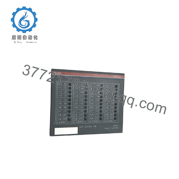
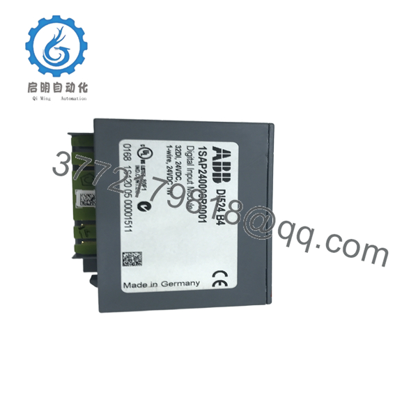
The ABB DI524 (1SAP240000R0001) is a 32-channel 24 V DC digital input module for the AC500 S500 distributed I/O platform. It acquires field signals from sensors, pushbuttons, limit switches, and auxiliary contacts, transferring the data to the AC500 PLC over the S500 backplane.
In field installations, the DI524 is frequently used in machine automation, material handling systems, water treatment plants, and process industries where high-density digital input capability is required. Its configurable input filter helps suppress signal noise, while IEC 61131-2 Type 1 input characteristics ensure compatibility with standard 24 V DC industrial devices. Before replacing an existing module, verify the CPU firmware revision and hardware configuration.

- DI524
- DI524
5. Installation & Configuration Guide
Stage 1 – Pre-Installation Preparation (Estimated Time: 10 Minutes)
⚠️ Safety First
- Notify operations personnel of the planned shutdown.
- Bring the controlled equipment to a safe state.
- Apply Lockout/Tagout procedures.
- Disconnect the 24 V DC control supply.
- Wait at least 5 minutes before opening the cabinet.
Tools Required
- Grounded ESD wrist strap
- PH1 screwdriver
- Fluke 115 digital multimeter
- Wire identification labels
- Smartphone for wiring documentation
Data Backup
Before removing the module:
- Save the PLC project.
- Record hardware configuration.
- Photograph all terminal wiring.
- Document channel assignments.
- Record CPU firmware version.
Stage 2 – Removing the Old Module (Estimated Time: 10 Minutes)
- Remove cabinet power.
- Label every field wire.
- Disconnect the terminal unit.
- Release the module locking mechanism.
- Pull the module straight from the S500 bus.
⚠️ Do not rock the module side-to-side. Excessive force can damage the backplane connector.
Inspect:
- DIN rail
- Terminal unit
- Bus connector
- Wiring insulation
Keep the original module available until commissioning is complete.
Stage 3 – Installing the New Module (Estimated Time: 10 Minutes)
- Wear an ESD wrist strap.
- Verify the replacement is ABB DI524 (1SAP240000R0001).
- Install the module onto the S500 backplane.
- Reinstall the terminal unit.
- Restore field wiring.
Configuration Check
Verify:
- PLC hardware configuration
- Channel addressing
- Input filter settings
- Firmware compatibility
Self-Checklist
- ✅ Module fully seated
- ✅ Wiring secured
- ✅ Hardware configuration verified
- ✅ Terminal unit locked
Stage 4 – Power-On & Testing (Estimated Time: 15 Minutes)
Pre-Power Inspection
- Verify 24 V DC polarity.
- Measure for shorts.
- Confirm cabinet grounding.
Startup Procedure
- Energize the PLC rack.
- Verify the module status LED.
- Observe individual input LEDs.
- Test each input device.
- Confirm PLC diagnostics report normal operation.
- Verify all field devices respond correctly.
⚠️ Troubleshooting Notes
Input LEDs remain OFF
- Verify field voltage exceeds the ON threshold.
- Check common return wiring.
Module Fault
- Compare the installed hardware configuration with the PLC project.
- Verify CPU firmware supports the installed module.
Intermittent Inputs
- Increase the configurable input filter if electrical noise is present.
- Inspect sensor wiring and grounding.
6. Frequently Asked Questions (FAQ)
Q1. Can the DI524 be hot-swapped?
Only when installed with the appropriate ABB hot-swap terminal unit. Even then, evaluate the impact on the running process before replacing the module in a live system. Many maintenance teams still schedule a controlled shutdown to eliminate unnecessary risk.
Q2. What types of field devices can connect to the DI524?
The module accepts standard 24 V DC digital signals from proximity sensors, photoelectric sensors, pushbuttons, selector switches, auxiliary relay contacts, and limit switches that comply with IEC 61131-2 Type 1 input requirements.
Q3. Will replacing the DI524 affect the PLC application?
No. The application program remains stored in the CPU. However, the PLC hardware configuration must match the installed I/O module. I’ve seen technicians replace a perfectly good module only to discover the CPU was configured for a different slot assignment.
Q4. What is the most common installation mistake?
The mistake I encounter most often is reconnecting multiple input commons without documenting the original wiring. Thirty seconds spent photographing the terminal block before removal can save hours of troubleshooting afterward.
Q5. Does the DI524 include channel diagnostics?
Yes. The module provides individual channel status LEDs and diagnostic information through the AC500 engineering environment, making it easier to identify missing field voltage, wiring faults, or inactive input channels.
Q6. Is this module compatible with decentralized I/O systems?
Yes. The DI524 can be used in central AC500 racks or decentralized S500 I/O stations through supported communication interface modules, including PROFINET IO, PROFIBUS DP, EtherCAT, Modbus TCP, CANopen, and CS31. Compatibility depends on the selected interface module and system architecture.
Q7. What should I verify before ordering a replacement?
Confirm the following before placing an order:
- Exact model: DI524
- Product ID: 1SAP240000R0001
- Terminal unit: TU515 or TU516
- CPU firmware version
- PLC hardware configuration
- Required channel count (32 × 24 V DC inputs)
Those checks eliminate most replacement issues and help restore production with minimal downtime.



