
 WhatsApp: +86 16626708626
 Email:
  Phone: +86 16626708626
Description
Key Technical Specifications
| Parameter | Specification |
| Manufacturer Model | IMRIO02 |
| System Architecture | ABB Bailey INFI 90 / Network 90 DCS |
| Power Consumption | +5 V DC @ 1.2 A (Backplane supply) |
| Bus Compatibility | Expander Bus (MEB) / Remote I/O Serial Link |
| Data Transmission Rate | High-speed synchronous serial communication |
| Isolation | Optically isolated transmission line drivers |
| Diagnostics | Front-panel LED status indicators (ONLINE, FAULT, BUS ACTIVITY) |
| Module Slot | Standard INFI 90 Module Mounting Unit (MMU) slot |
| Operating Temperature | 0°C to +70°C (32°F to 158°F) |
| Humidity | 5% to 95% non-condensing |
Product Introduction & Supply Chain Strategy
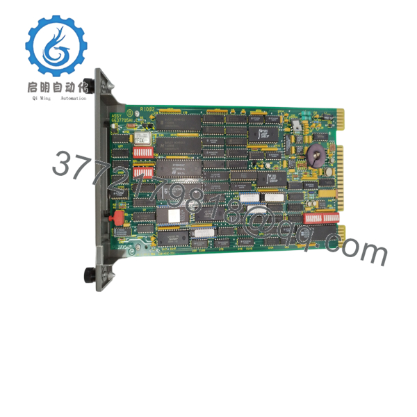
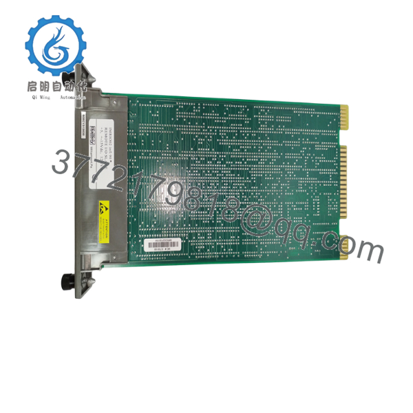
The ABB Bailey IMRIO02 Remote I/O Interface Module expands the architecture of ABB INFI 90 and Network 90 systems. Positioned in a central Module Mounting Unit (MMU), it establishes a dedicated, high-speed serial link between primary process execution units (such as the IMMFP01 Multi-Function Processor) and geographically distributed remote I/O drops across the plant.
This unit is supplied as Brand New Surplus stock—never deployed, pulled from decommissioned panels, or rebuilt. Installing used or pulled I/O interface cards in continuous process plants introduces serious operational risks: degraded optical isolation couplers, thermal fatigue on line drivers, and intermittent signal drops across the remote bus. A loss of communication between the central processor and remote field blocks can blind control loops, causing emergency safety trips that result in tens of thousands of dollars in unmonitored downtime. Sourcing a verified New Surplus IMRIO02 module guarantees immediate drop-in restoration, pristine line communication, and long-term operating stability for legacy DCS networks.

- IMRIO02
- IMRIO02
Installation & Configuration Guide
Stage 1: Pre-Installation (Prep & Safety)
- Execute full Lock-Out/Tag-Out (LOTO) on the MMU power chassis and cabinet main feeds.
- Strap on a grounded ESD wrist cuff connected to cabinet chassis ground before opening static-shielding packaging.
- Record all hardware jumper locations, address DIP switch positions, and termination settings from the existing IMRIO02 module.
- Clean the MMU backplane card slot using dry compressed air to remove dust or particulate accumulation.
Stage 2: Removal
- Unplug front panel serial communications cables and remote bus connectors.
- Unfasten the top and bottom retaining screws securing the module faceplate to the MMU frame.
- Pull the ejector handles outward to disengage the board’s edge connectors from the backplane, then slide the card out along its guide tracks.
Stage 3: Installation (Clone & Seat)
- Set all onboard DIP switch blocks and configuration jumpers on the new IMRIO02 module to mirror the removed card exactly.
- Align the IMRIO02 board with the top and bottom guide rails in the designated MMU slot.
- Slide the card inward until the rear connectors reach the backplane, then press the faceplate ejector handles firmly until the module locks into place.
- Tighten the top and bottom retention screws to hand tightness (0.5 N·m).
Stage 4: Power-On & Testing
- Reconnect front-panel remote I/O bus cables and field link connectors.
- Energize the MMU power chassis and observe the front faceplate LED initialization sequence.
- Confirm the green ONLINE LED lights up solid and no red FAULT indications appear.
- Verify remote I/O channel communication and data updates through Composer or WinCAD engineering software.
Firmware/Software Versions & Upgrade Notes
- System Compatibility: Compatible with ABB INFI 90, Network 90, and Symphony Harmony control architectures.
- Hardware Matching: Ensure hardware revision codes and dip-switch bus address configurations match original cabinet schematics.
- Hot-Swap Caution: Never extract or insert the IMRIO02 module while the MMU backplane is energized. Power down the targeted rack section prior to card replacement to prevent bus communication spikes or voltage transients.
Frequently Asked Questions (FAQ)
Is this ABB IMRIO02 module brand new or refurbished?
This product is a Brand New Surplus unit. It is guaranteed unused, fully intact, and thoroughly inspected prior to dispatch.
What is the primary role of the IMRIO02 in an INFI 90 DCS system?
The IMRIO02 serves as a dedicated remote I/O interface that links central processing modules (like the IMMFP01 processor) with distant expansion racks and remote I/O sub-nodes over a high-speed serial bus.
How does the IMRIO02 differ from the IMMFP01 and IEMMU21 modules?
While the IMMFP01 acts as the core processing engine executing control algorithms and the IEMMU21 manages local MMU bus extension, the IMRIO02 specifically manages high-speed serial links to remote, distributed field I/O racks.
What causes communication faults on the IMRIO02 remote bus?
Common causes include incorrect DIP switch node addressing, missing or improper 120-ohm bus termination resistors, damaged shielding, or failed optical isolators on aging cards.
What documentation and warranty accompany this module?
All New Surplus ABB IMRIO02 cards ship in ESD shielding bags with factory serial tags, QC inspection documentation, and a full 1-year operational replacement warranty.



