WhatsApp: +86 16626708626
 Email:
 Phone: +86 16626708626
Description
Core Product Summary
The ABB PCS6000 is a medium-voltage full-power converter for large wind turbines, rated at a nominal converter voltage of 3.3 kV and covering generator power ratings up to 15 MW. It belongs to ABB’s utility-scale wind converter portfolio and uses a 3-level, 4-quadrant VSI-NPC (voltage source inverter with neutral-point-clamped) topology with a fuseless design and IGCT semiconductors.
The converter fully decouples the generator from the grid, providing independent generator-side pulse-width-modulation control and grid-side optimized pulse pattern control, with fault ride-through capability and grid code compliance functions. Cooling is handled by a closed-loop liquid cooling unit using a deionized water/glycol coolant. The PCS6000 supports permanent magnet, asynchronous induction, and static-excited synchronous generators, and can be arranged for nacelle or tower-base installation in in-line, back-to-back, face-to-face, or T-shape cabinet layouts.
Key Technical Specifications
| Parameter | Value |
|---|
| Product type | Medium-voltage full-power wind turbine converter |
| Converter topology | 3-level, 4-quadrant, VSI-NPC, fuseless design |
| Semiconductor type | IGCT (integrated gate-commutated thyristor) |
| DC-link capacitors | Self-healing, self-protected film capacitors |
| Generator power range | Up to 15 MW |
| Nominal converter voltage | 3.3 kV |
| Generator-side voltage | 0 to 3.4 kV |
| Grid-side voltage | 0 to 3.4 kV |
| Generator-side frequency | 0 to 120 Hz (other frequencies on request) |
| Grid-side frequency | 50/60 Hz |
| Efficiency at rated point | Approx. 98% |
| Generator-side du/dt | < 1.5 kV/µs |
| Generator-side control | Pulse width modulation |
| Grid-side control | Optimized pulse pattern |
| Fieldbus interfaces | Profibus DP, Profinet IO, Modbus TCP, EtherCAT, CANopen |
| Service access | Ethernet via installed IPC with Windows-based software tool; VPN remote access ready |
| Cooling | Closed-loop liquid cooling unit, deionized water/glycol coolant |
| Cooling pumps | 1 pump, or 2 pumps with automatic changeover |
| Coolant inlet temperature | Up to 45 °C (higher on request) |
| Ambient temperature | Operation −10 to +45 °C; storage −25 to +55 °C; transport −25 to +70 °C |
| Altitude | 0 to 1000 m |
| Degree of protection | IP54 |
| Auxiliary supply | 3-phase 400 V, 50/60 Hz |
Engineering Selection Highlights
- 3.3 kV nominal voltage with 0–3.4 kV generator- and grid-side ranges → confirms the converter is intended for medium-voltage drivetrains; turbine generator and transformer must be specified for the MV interface rather than a low-voltage connection.
- IGCT-based 3-level 4-quadrant VSI-NPC topology, fuseless design → bidirectional power flow supports both generating and motor operation, and the low parts count without component paralleling simplifies spare-parts planning.
- Support for permanent magnet, asynchronous induction, and static-excited synchronous generators at high, medium, and low speeds → the same converter platform can be matched to different turbine drivetrain concepts rather than being tied to one generator type.
- Fieldbus options including Profibus DP, Profinet IO, Modbus TCP, EtherCAT, and CANopen → the converter integrates with the turbine master controller over common industrial networks; the required interface must be confirmed at order configuration.
- Closed-loop liquid cooling with coolant inlet up to 45 °C and optional redundant pumps → cooling-water supply infrastructure at the tower base or nacelle must be planned; pump redundancy is a configuration decision affecting availability.
- Operation envelope of −10 to +45 °C, 0–1000 m altitude, IP54 → site conditions outside these limits (high altitude, extreme cold) require project-specific clarification rather than standard configuration.
- Dynamic braking chopper with IGCT and 15 MJ or 30 MJ braking resistor options → low-voltage ride-through and controlled shutdown depend on the selected resistor capacity, which also affects cabinet footprint and weight.
PCS6000
System Compatibility & Integration Requirements
| Item / Dependency | Verified Compatibility or Requirement | Practical Note |
|---|
| Turbine generator | High-, medium-, and low-speed PM generators; asynchronous induction generators; static-excited synchronous generators | Generator type is a configuration input for the control setup |
| Controller | ABB AC 800PEC high-performance controller | Governs generator-side and grid-side control and grid code functions |
| Turbine controller interface | Profibus DP, Profinet IO, Modbus TCP, EtherCAT, CANopen | Fieldbus option must match the turbine master control system |
| Service and monitoring | Installed IPC with Windows-based software tool; Ethernet access; VPN remote access ready | Enables trending, data logging, and transient recording |
| Cooling system | Closed-loop unit with deionized water/glycol coolant; water-air (external) or water-water (internal) heat exchanger; coolant connections DN80 from top | External cooling-water circuit or heat exchanger must be provided at the installation site |
| Auxiliary power | 3-phase 400 V, 50/60 Hz; approx. 8–12 kW depending on rating | Auxiliary supply must be available in the turbine or tower base |
| Grid codes | Active and reactive grid power control with fault ride-through (high- and low-voltage ride-through) | Grid-code-specific rating and settings are defined per project |
| Installation location | Nacelle or tower base; in-line, back-to-back, face-to-face, or T-shape arrangements | Arrangement choice depends on available turbine platform space |
Dimensions, Mounting & Connection Notes
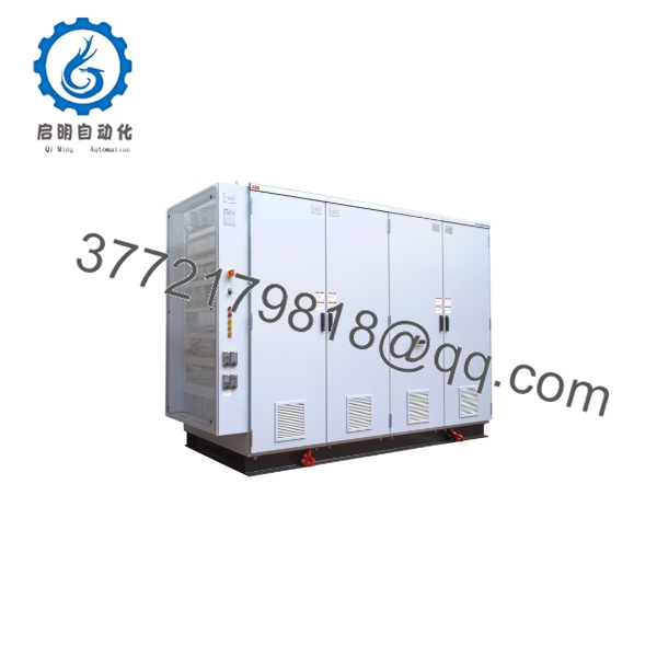
The PCS6000 is built as a modular cabinet lineup on a solid base frame using 1.5 mm carbon-steel, edge-bended sheets (MNS system construction, riveted and bolted), powder- and/or zinc-coated in RAL 7035, with IP54 protection. Doors use mechanical security interlocking with release when grounded. Lifting is from the bottom via removable eyebolts. Anticondensation protection is provided by humidity and temperature sensors with control logic and space heaters.
Dimensions and weights depend on the power rating and cabinet arrangement. Documented example configurations:
| Configuration | In-line arrangement (L×W×H) | Weight |
|---|
| 7 MW / 8.5 MVA | 4960 × 1280 × 2460 mm | ~5300 kg |
| 10 MW / 12 MVA | 5160 × 1280 × 2460 mm | ~6200 kg |
| 12 MW / 14.5 MVA | 5960 × 1280 × 2460 mm | ~7300 kg |
T-shape, face-to-face, and back-to-back arrangements are documented with rating-dependent dimensions (for example 4360 × 2100 × 2460 mm T-shape and 3550 × 2280 × 2450 mm back-to-back for selected ratings); some combinations are engineered on request.
Power connections: generator-side and grid-side cable entries are from the top using Pfisterer P3 connections; the braking resistor connects from the back (Pfisterer P3); control wiring enters from the bottom to terminals inside the control cabinet. Coolant connections are DN80 from the top. The braking resistor itself is air-cooled, approximately 1160 × 670 × 660 mm at ~200 kg (15 MJ) or 1160 × 670 × 1030 mm at ~400 kg (30 MJ).
Detailed Product Overview
The PCS6000 applies medium-voltage converter technology to wind turbines whose power ratings have outgrown practical low-voltage solutions. At 3.3 kV, currents are substantially lower than in an equivalent low-voltage design, which reduces losses in the generator, converter, and cabling and allows more compact cable runs between the nacelle and tower base. The converter is implemented as a 3-level, 4-quadrant voltage source inverter with neutral-point clamping, built around IGCT semiconductors. IGCTs handle the full converter current without paralleling of components, keeping the parts count low; documented configurations use 12 + 12 IGCTs at the lower ratings and up to 24 + 24 at the highest. Self-healing, self-protected film capacitors form the DC link, which electrically decouples the generator side from the grid side so a disturbance on one side does not propagate directly to the other.
Control is split by function: the generator side uses pulse width modulation for active and reactive generator power control, while the grid side uses optimized pulse patterns for grid code compliance. Both are executed by ABB’s AC 800PEC controller. The control layer also implements drivetrain damping, which reduces mechanical stress on the gearbox and shaft during grid disturbances, and overspeed and overvoltage protection. For commissioning and service, the converter supports motor operation — running the generator as a motor for hall tests, back-to-back testing, and precise rotor positioning — plus special modes for static VAr compensation and island operation.
Thermal management uses a closed-loop cooling unit circulating a deionized water/glycol mixture, with automatic deionization and deaeration, temperature control via a motor-driven valve, and either an external water-air or internal water-water heat exchanger. One pump is standard; a second pump with automatic changeover is available where cooling redundancy is required.
Mechanically, the converter is delivered as a modular cabinet lineup that can be configured in-line, back-to-back, face-to-face, or T-shape, so it can be fitted to a single deck in the nacelle or placed at the tower base. Tower-base installation reduces nacelle weight and simplifies service access, while nacelle installation shortens the MV cable route to the generator. Fault ride-through capability — both low- and high-voltage ride-through, supported by the dynamic braking chopper and resistor — keeps the turbine connected through grid disturbances, and the precharging soft start synchronizes to the grid without inrush current or flicker. Monitoring is handled through an installed IPC with a Windows-based software tool, high-resolution transient recording, trending, and data logging, with VPN remote access readiness for remote diagnostics.
Applications & System Role
The PCS6000 sits between the wind turbine generator and the MV collection grid or transformer as the full-power conversion stage: all generated power passes through the converter, which rectifies the variable-frequency generator output and inverts it to a grid-synchronous 50/60 Hz supply. This architecture decouples the mechanical drivetrain from grid behavior, so turbine speed can be optimized for energy capture while the grid side independently manages active and reactive power to meet grid code requirements.
Within the turbine’s electrical system, the converter also provides functions beyond power conversion: precharging soft start for inrush-free grid synchronization, dynamic braking chopper operation for low-voltage ride-through and controlled shutdown, island mode to supply turbine auxiliaries when disconnected from the grid, and motor operation for full-speed drivetrain testing and precise rotor positioning during installation and maintenance.
The platform is designed for large onshore and offshore turbines in the multi-megawatt class and, as a medium-voltage full-power converter, is technically suited to high-power renewable applications of similar structure, such as tidal or wave energy conversion.
FAQ
What is the ABB PCS6000? The ABB PCS6000 is a medium-voltage full-power converter for large wind turbines. It converts the variable-frequency output of the turbine generator into grid-synchronous 50/60 Hz power at a nominal voltage of 3.3 kV, covering generator power ratings up to 15 MW.
What converter topology does the PCS6000 use? It uses a 3-level, 4-quadrant VSI-NPC (voltage source inverter, neutral-point-clamped) topology with IGCT semiconductors, a fuseless design, and self-healing film capacitors in the DC link.
Which generators can the PCS6000 operate with? The converter supports high-, medium-, and low-speed permanent magnet generators, asynchronous induction generators, and static-excited synchronous generators.
What cooling system does the PCS6000 require? The converter is liquid-cooled by a closed-loop cooling unit using a deionized water/glycol coolant, with coolant inlet temperatures up to 45 °C. It can be configured with one pump or two pumps with automatic changeover, and with an external water-air or internal water-water heat exchanger.
Which communication interfaces are available? Fieldbus options include Profibus DP, Profinet IO, Modbus TCP, EtherCAT, and CANopen. Service and maintenance access is provided via Ethernet through an installed IPC with a Windows-based software tool, and the unit is VPN remote access ready.
Where can the PCS6000 be installed in a wind turbine? The converter is designed for nacelle or tower-base installation. Its modular cabinets can be arranged in-line, back-to-back, face-to-face, or in a T-shape layout to fit the available turbine platform space.
What are the PCS6000’s environmental operating limits? Operating ambient temperature is −10 to +45 °C at altitudes from 0 to 1000 m, with IP54 enclosure protection. Storage range is −25 to +55 °C and transport range is −25 to +70 °C.
Does the PCS6000 support fault ride-through? Yes. The converter provides high- and low-voltage ride-through to keep the turbine online during grid disturbances, supported by a dynamic braking chopper with 15 MJ or 30 MJ braking resistor options for ride-through and controlled shutdown.