
 WhatsApp: +86 16626708626
 Email:
  Phone: +86 16626708626
Description
Key Technical Specifications
| Parameter | Value |
|---|---|
| Manufacturer | ABB |
| Model Number | SNAT 7261 PCP |
| Alternate Search Format | SNAT7261PCP |
| Known Order Reference | 57618809; verify the marking on the installed board before procurement |
| Product Type | Main interface board / QCP control board / drive control PCB |
| Product Family | ABB SNAT 7261 board family |
| Primary Function | Coordinates internal drive control and interface functions |
| Referenced Functions | Internal auxiliary power generation, gate-pulse triggering, DC-link sensing, and phase-current sensing |
| Associated Board Reference | SNAT0503BDB appears in market listings as a related or matching board; compatibility must be confirmed from the drive’s bill of materials |
| Installation Location | Internal ABB drive cabinet or drive control assembly; exact position varies by drive model and revision |
| Supply Source | Provided through the host ABB drive electronics; do not apply external power directly to the board unless ABB documentation explicitly instructs it |
| Field Configuration | Inspect and document jumpers, DIP switches, link positions, connector keys, and revision labels before replacement |
| Lifecycle Status | Legacy spare / elevated obsolescence exposure |
| Stocking Recommendation | Min: 1 verified board per critical compatible drive family; Max: 2 only where multiple installed drives share the exact board revision and production downtime risk supports the carrying cost |
| Incoming QC Requirement | Verify order reference, board revision, component-side markings, connector layout, firmware or PROM devices, conformal coating condition, and zero bent or oxidized pins |
Public seller information describes the SNAT 7261 PCP as a QCP drive control board and identifies a related SNAT0503BDB board reference. Another listing describes board-level functions including internal auxiliary power generation, gate-pulse triggering, high-speed DC-link sensing, and phase-current sensing. These descriptions should be treated as preliminary identification and verified against the specific ABB drive documentation before installation.
Product Introduction & Supply Chain Strategy
The ABB SNAT 7261 PCP is an internal drive-control interface board used in compatible ABB legacy drive assemblies. It supports control-board functions that may include auxiliary-power handling, gate-pulse control, DC-link measurement, and phase-current feedback, enabling the drive to monitor and regulate its power stage. The exact drive model, board revision, and mating-board configuration must be confirmed from the installed equipment before ordering.
This product is a Brand New Surplus unit. It is not used, not pulled from a decommissioned plant, and not refurbished. All modules undergo rigorous quality verification to ensure OEM-level reliability. For a legacy drive board, a single verified buffer stock unit often provides the best Total Cost of Ownership (TCO): it prevents extended outages while avoiding unnecessary capital tied up in duplicate inventory. Use vendor consolidation, revision control, and cross-site sharing before expanding Max stock.
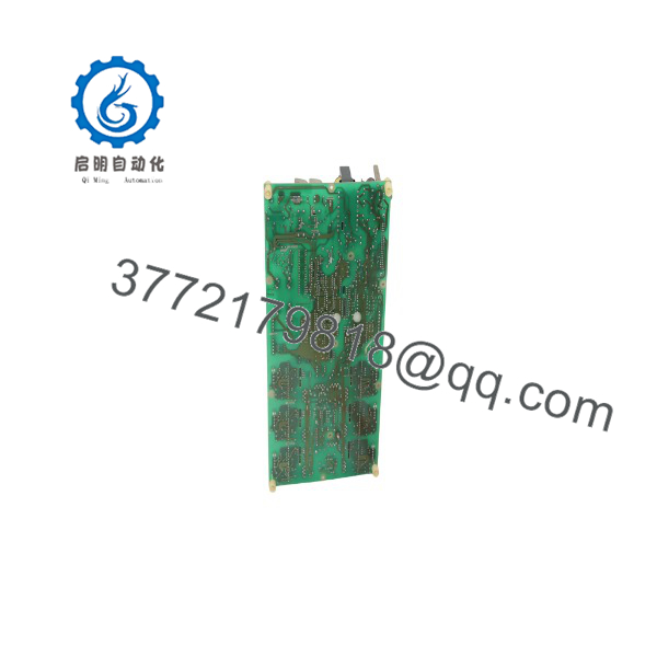
SNAT 7261 PCP
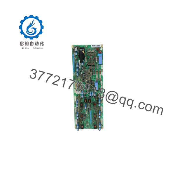
SNAT 7261 PCP
Installation & Configuration Guide
Stage 1: Pre-Installation
- Stop the driven equipment using the approved operating procedure. Record all drive fault codes, alarm history, operating status, command source, speed reference, and process conditions before shutdown.
- Apply lock-out/tag-out to incoming line power, control power, external 24 V circuits, motor circuits, fieldbus or control interlocks, and stored mechanical energy connected to the driven machine.
- Verify that incoming power is absent with properly rated test equipment. ABB drive DC buses can retain hazardous voltage after isolation, so wait for the documented discharge time and verify DC-link voltage before touching internal assemblies.
- Wear a grounded ESD wrist strap and work on an ESD-safe surface. The SNAT 7261 PCP is a static-sensitive control board.
- Photograph the installed board from both accessible sides before removal. Capture the ABB drive model, serial number, board order code, PCB revision, labels, connector identifiers, cable colors, jumper links, DIP-switch positions, PROM or memory-device labels, and mounting arrangement.
- Save all available drive parameter sets, control macros, motor data, speed-reference settings, I/O assignments, fieldbus settings, fault-history records, and firmware information.
- Confirm the replacement board is an exact match for SNAT 7261 PCP and the installed board’s order reference, component layout, revision, connector pattern, and configured devices. Do not rely on the SNAT family name alone.
- Inspect the drive for root-cause evidence: damaged snubber components, failed cooling fans, blocked airflow, loose power connections, ground faults, blown fuses, contaminated boards, failed gate-drive components, or DC-link capacitor deterioration. A replacement control board can fail immediately if the underlying power-stage fault remains.
Stage 2: Removal
- Confirm the DC-link voltage is at a safe level according to the ABB drive documentation before opening the control compartment.
- Label every cable and connector individually, even if factory markings are visible. Legacy panels often contain modified wiring that differs from original drawings.
- Disconnect ribbon cables, plug-in harnesses, fiber-optic links, and feedback connectors by their housings. Do not pull on wire bundles or twist connector bodies.
- Remove any board retaining screws, clips, standoffs, or shielding hardware in the documented sequence. Keep hardware segregated so grounding screws and insulating spacers return to their original locations.
- Extract the board evenly and vertically where practical. Avoid flexing the PCB, scraping components against the chassis, or bending mating pins.
- Inspect all connectors, card guides, standoffs, ground contacts, and cable terminations. Correct oxidation, loose contacts, heat damage, or bent pins before installation.
- Preserve the original board in an ESD-safe bag and label it with the drive asset number, fault symptoms, removal date, and parameter-backup location for engineering analysis.
Stage 3: Installation
- Compare the New Surplus SNAT 7261 PCP board to the removed board side by side. Confirm the exact order reference, revision markings, connector count, connector keying, component population, PROM or firmware devices, jumper links, and mounting-hole locations.
- Replicate all documented DIP-switch and jumper configurations exactly. Do not assume factory-default link positions match the existing drive application.
- If the original board contains removable firmware, PROM, configuration memory, or site-specific devices, transfer them only when ABB documentation confirms that the device is reusable and compatible with the replacement board revision.
- Seat the board carefully on its guides, standoffs, or mating connectors. Apply even pressure only at designated areas; do not press on relays, transformers, connectors, or integrated circuits.
- Reinstall retaining hardware, shielding, and ground straps exactly as documented. Missing ground hardware can introduce noise, sensing faults, or gate-drive instability.
- Reconnect each cable by its recorded identifier. Confirm connector keying before insertion; never force a plug that does not align naturally.
- Inspect the assembled control compartment for loose screws, displaced insulating barriers, unseated connectors, pinched wiring, or tools left in the enclosure.
- Recheck power-stage wiring and motor insulation if the original fault involved overcurrent, ground fault, DC-link fault, or gate-drive failure.
Stage 4: Power-On & Testing
- Before applying full drive power, test the control-power rail and relevant low-voltage supplies for shorts to ground.
- Apply control power first if the ABB drive architecture permits. Observe control-board indicators, display messages, and diagnostic LEDs for normal initialization.
- Do not issue a run command until the drive reports ready status and no internal control, feedback, current-sensing, gate-drive, or DC-link alarms remain.
- Verify the drive parameter set, motor data, I/O mapping, fieldbus communication, command source, speed-reference scaling, and safety interlock status.
- Command a low-speed no-load test with the driven machine in a safe condition. Confirm motor direction, current feedback, speed feedback, DC-link stability, and absence of abnormal noise or vibration.
- Increase speed and load gradually while monitoring drive current, output voltage, fault history, heatsink temperature, DC bus behavior, and process response.
- Return the machine to automatic production only after completing the site’s documented functional acceptance test. Record the replacement board’s serial number, board revision, installation date, parameter revision, fault findings, and remaining buffer stock.
Firmware/Software Versions & Upgrade Notes
- Recommended firmware version: Retain the installed drive’s validated firmware, PROM, and parameter configuration during a direct SNAT 7261 PCP board replacement. Public sources do not provide an ABB-controlled firmware matrix for this exact board, so the existing board labels, ABB drive manual, installed drive identity, and approved site backup are the required reference points.
- Board revision control: Match the removed board’s exact ABB order reference and PCB revision wherever possible. Different revisions can alter connector assignments, signal thresholds, gate-pulse behavior, power-supply interfaces, or compatibility with associated boards.
- Associated-board compatibility: Market data associates SNAT0503BDB with SNAT7261PCP. Verify the complete control-board stack and drive bill of materials before installation; a compatible-looking board combination is not proof of system compatibility.
- Parameter retention: The drive’s parameter set may reside in the main control board, removable memory, operator panel, or external engineering backup. Back up parameters before removal and verify restoration after installation.
- Backward compatibility: Earlier board revisions may not support later PROM versions, firmware configurations, drive I/O options, or communication interfaces. Do not install a lower revision simply because it fits mechanically.
- Forward compatibility: A later revision may require different firmware, parameter initialization, or associated control-board revisions. Treat it as an engineered change unless ABB documentation explicitly approves direct substitution.
- Upgrade warning: Do not perform firmware upgrades while correcting an emergency board failure unless the original firmware is unavailable and the upgrade has passed a documented compatibility review. Firmware changes can affect I/O timing, fieldbus operation, fault behavior, and motor-control performance.
- Downgrade warning: Do not downgrade firmware or transfer memory devices without a verified recovery plan. A failed transfer can leave the drive unable to initialize.
- Spare-control recommendation: Store the New Surplus board with an ESD-safe label that identifies the compatible drive model, exact board revision, parameter-backup location, firmware or PROM information, related board requirements, and the approved commissioning checklist.
Frequently Asked Questions (FAQ)
Are these really new units?
Yes. This supply standard is for New Original / New Surplus inventory only. A New Surplus SNAT 7261 PCP board should show no installation wear, connector-pin damage, soldered field repairs, contamination, heat discoloration, corrosion, or altered components. Incoming inspection should verify the ABB markings, order reference, PCB revision, connector condition, component population, ESD-safe packaging, and serial or traceability documentation where available.
Why is New Surplus pricing lower than OEM new but higher than lower-cost alternatives?
OEM-new pricing reflects active manufacturer supply channels and standard support structures. New Surplus pricing reflects the cost of locating, validating, storing, and warranting genuine legacy control boards after normal supply becomes constrained. Lower-cost alternatives may conceal damaged traces, overstressed gate-drive circuits, capacitor aging, poor solder work, altered component values, or incompatible board revisions. Saving a few hundred dollars can create a much larger loss if a critical drive remains down or fails again under load.
Is the ABB SNAT 7261 PCP obsolete or EOL?
Treat the SNAT 7261 PCP as a legacy ABB drive spare with elevated obsolescence exposure. Public market listings indicate continuing secondary-market demand, but they do not establish active ABB production or direct replacement status.
For a production-critical compatible drive, keep one verified on-site board. Conduct a last-time-buy review when available stock declines, supplier lead time variability increases, or the installed base remains active beyond the expected lifecycle of the drive. Avoid excess inventory by confirming exact board commonality across plants before purchasing a second unit.
Can I hot-swap the SNAT 7261 PCP board?
No. Do not install or remove this control board while the drive is energized. The board interfaces with the drive control system and may relate to gate-pulse, current-sensing, auxiliary-power, and DC-link functions. Isolate all power, verify discharge of the DC bus, use ESD controls, and follow the ABB drive service procedure before handling the board.
Will replacing the board erase the drive programming?
It can. Parameters, configuration data, firmware, PROM devices, and communication settings may reside on the board, in removable memory, an operator panel, or an external backup. Save the parameter set before removal, photograph installed firmware or memory labels, and verify all motor, I/O, communication, and control settings after installation.
Can I substitute another SNAT 7261 board?
Not without an engineering-approved cross-reference. SNAT 7261 PCP, SNAT 7261 SCP, SNAT 7261 INT, and other similarly named boards may have different functions, connector assignments, component populations, firmware requirements, or drive applications. Match the full ABB order reference, PCB revision, installed drive model, associated board stack, and configuration devices before authorizing a substitution.
What warranty and quality documentation should be required?
Specify a written 12month warranty, subject to correct ESD-safe storage, installation, and operating conditions. Request order-reference photographs, PCB revision photographs, component-side and solder-side inspection records, connector and pin-condition checks, power-on or functional-test evidence where a compatible test fixture is available, and final QC sign-off. Keep these records with the drive asset history to shorten future troubleshooting and replacement time.



