
 WhatsApp: +86 16626708626
 Email:
  Phone: +86 16626708626
Description
Key Technical Specifications
| Parameter | Value |
|---|---|
| Model | cPS-H325/24 |
| Manufacturer | ADLINK Technology |
| Product Type | CompactPCI hot-swap power module |
| CompactPCI Standard | PICMG 2.11 |
| Form Factor | 3U CompactPCI, 8HP wide |
| Dimensions | 100 × 160 mm |
| Power Rating | 250 W typical continuous |
| Input Voltage | 18–36 VDC |
| Input Current | 32.6 A peak at 24 VDC |
| Output Rails | +5 V, +3.3 V, +12 V, −12 V |
| +5 V Output | 25 A typical, 33 A maximum |
| +3.3 V Output | 18 A typical, 33 A maximum |
| +12 V Output | 5 A typical, 5.5 A maximum |
| −12 V Output | 0.5 A typical, 1 A maximum |
| Power Interface | PICMG 2.11, 47-pin |
| Redundancy | N+1, internal OR-ing diodes |
| Hot-Swap | Yes |
| Current Sharing | Active current sharing |
| Remote Control | Remote ON/OFF |
| Power-Fail Signal | Available through FAL# |
| Degradation Signal | Available through DEG# |
| Hold-Up Time | 5 ms after power-fail signal |
| Line Regulation | Typical 0.1% |
| Load Regulation | Typical ±1–2% |
| Ripple | 50 mV at 5 V / 3.3 V; 120 mV at ±12 V |
| Operating Temperature | −40 °C to +70 °C at full load with specified airflow |
| Storage Temperature | −45 °C to +85 °C |
| Cooling | Forced-air cooling required for rated operation |
| Status Indicators | POWER and FAULT LEDs |
ADLINK specifies the cPS-H325/24 as a 47-pin PICMG 2.11 hot-swap redundant power module. Its four output rails are +5 V, +3.3 V, +12 V, and −12 V. The individual maximum rail currents cannot all be drawn simultaneously; the overall module remains a 250 W-class power supply.
The manufacturer’s documentation also specifies internal OR-ing diodes, active current sharing, remote ON/OFF control, power-failure signaling, and a degradation signal.
Product Introduction
The ADLINK cPS-H325/24 is a 3U CompactPCI power module designed for systems using the PICMG 2.11 power interface. It accepts 18–36 VDC input and provides +5 V, +3.3 V, +12 V, and −12 V output rails with a typical continuous power rating of 250 W.
The module is intended for redundant CompactPCI chassis where hot-swap replacement and N+1 operation matter. Internal OR-ing diodes and active current sharing support redundant power architectures, while remote ON/OFF and power-status signals allow the chassis controller to monitor the supply.
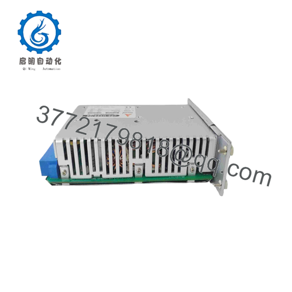
cPS-H325/24
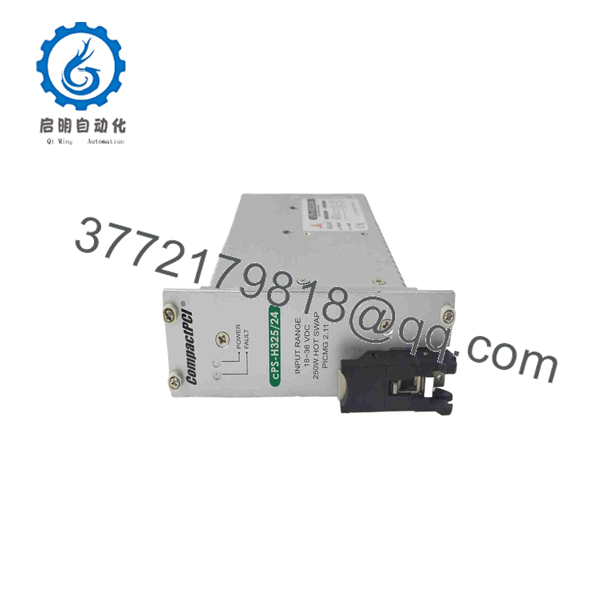
cPS-H325/24
Installation & Configuration Guide
Stage 1: Pre-Installation Preparation — Approximately 5 Minutes
⚠️ Safety First: Notify operations, place the controlled system in its approved safe state, and follow the chassis manufacturer’s LOTO procedure where required. Although the cPS-H325/24 is specified as hot-swappable, do not perform a live replacement unless the installed CompactPCI chassis explicitly supports hot-swap operation and the site’s procedure authorizes it.
Tools Required
- ESD wrist strap
- PH1/PH2 screwdriver as applicable
- Digital multimeter
- Wire/slot identification labels
- Smartphone or camera for documentation
Data Backup
- Record the chassis slot occupied by the power module.
- Photograph the front-panel labeling and LED condition.
- Record the existing power-module model and revision.
- Check whether the chassis uses N+1 or another redundant power configuration.
- Record the upstream 24 VDC source and protection device.
- Review the chassis power budget before replacement.
⚠️ Critical: Do not confuse cPS-H325/24 with the visually similar cPS-H325/48, cPS-/110, or cPS-/AC variants. Their input requirements differ. ADLINK specifies 18–36 VDC for the /24 version, while the /48 version uses 36–72 VDC and the /110 version uses 66–160 VDC.
Stage 2: Removing the Old Module — Approximately 5 Minutes
- Confirm the chassis replacement procedure permits hot-swapping.
- If hot-swap is not explicitly supported, remove system power before extraction.
- Verify that the replacement model is cPS-/24.
- Release the module’s extraction mechanism.
- Pull the power module straight out of the CompactPCI slot.
- Avoid contacting exposed connector pins.
- Inspect the backplane connector for contamination or physical damage.
- Place the removed module in an ESD-safe bag.
⚠️ Keep the old module available for comparison until the replacement has completed startup and load checks.
Stage 3: Installing the New Module — Approximately 5 Minutes
- Attach the ESD wrist strap.
- Confirm the model marking: ADLINK cPS-/24.
- Verify the chassis is designed for the 8HP CompactPCI power-module format.
- Inspect the 47-pin connector.
- Align the module with the card guides.
- Insert the module straight into the backplane connector.
- Engage the extraction/retention mechanism.
- Confirm that the module is fully seated.
- If the chassis uses redundant supplies, verify that the companion power module remains online.
Self-Checklist
- cPS-/24 model confirmed
- 18–36 VDC input system confirmed
- 47-pin PICMG 2.11 interface confirmed
- Connector inspected
- Module fully seated
- Retention mechanism locked
- Redundant supply status checked
Stage 4: Power-On & Testing — Approximately 10–15 Minutes
- Confirm the chassis input supply is within the specified range.
- Energize the chassis according to the manufacturer’s procedure.
- Check the POWER LED.
- Check the FAULT LED.
- Measure the relevant output rail where the chassis design provides an appropriate test point.
- Verify +5 V, +3.3 V, +12 V, and −12 V rails against the system specification.
- Confirm that the chassis recognizes the power module.
- If operating in an N+1 configuration, verify load sharing and redundant operation.
- Monitor the module during initial system startup.
- Check for abnormal temperature, fan/airflow problems, or fault indications.
ADLINK specifies POWER and FAULT status indicators and provides power-failure and degradation signals through the CompactPCI power interface.
⚠️ Troubleshooting Note: If the POWER LED does not illuminate, check the 18–36 VDC input, chassis backplane connection, upstream protection, and hot-swap controller conditions. If the module reports a fault under load, check total chassis power consumption and airflow before replacing the module again.
Technical Pitfalls to Check Before Commissioning
1. Input Voltage Variant
❗ This is the most important identification check. cPS-/24 requires 18–36 VDC input. Installing a /48 or /110 variant in the wrong supply architecture can create an immediate compatibility problem.
2. Total Power vs. Individual Rail Ratings
Do not add every maximum rail current and assume the resulting number is available simultaneously. ADLINK explicitly notes that each rail’s maximum load cannot be drawn simultaneously from all outputs. The module’s typical continuous output rating is 250 W.
3. Airflow
The published thermal specifications depend on adequate chassis airflow. A module operating within its electrical rating can still experience thermal problems if the chassis fans, filters, or air path are restricted.
4. Redundancy Configuration
The cPS-/24 incorporates OR-ing diodes and active current sharing for N+1 operation. Confirm that the replacement is configured within the chassis’s intended redundant-power architecture.
5. Hot-Swap Assumption
❗ “Hot-swappable” does not mean “safe to remove from every CompactPCI chassis under every condition.” The chassis backplane, system controller, and operating procedure must support live power-module replacement.
Frequently Asked Questions (FAQ)
Can the ADLINK cPS-/24 be hot-swapped?
Yes, the module is designed as a hot-swap power module. ADLINK specifies hot-swapping as part of the product design. However, the specific CompactPCI chassis must also support the applicable hot-swap architecture and procedure.
What input voltage does the cPS-/24 require?
The specified input range is 18–36 VDC. Do not confuse it with the cPS-/48, which is designed for 36–72 VDC input, or the cPS-/110, which is designed for 66–160 VDC input.
What output voltages does the cPS-/24 provide?
It provides +5 V, +3.3 V, +12 V, and −12 V rails. The published typical output currents are 25 A, 18 A, 5 A, and 0.5 A respectively, with higher individual maximum ratings documented by ADLINK.
Is the cPS-/24 a 250 W power supply?
Yes. ADLINK identifies it as a 250 W DC output power module. The individual rail maximums cannot all be loaded simultaneously, so system engineers should perform a complete chassis power-budget calculation rather than simply summing the rail maximums.
Does it support N+1 redundant power operation?
Yes. The module incorporates internal OR-ing diodes and active current sharing for N+1 redundant operation. The chassis must also provide the appropriate redundant power architecture.
What is the difference between cPS-/24 and cPS-/24/CC?
The cPS-/24/CC is a conformal-coating variant. Mouser lists the /CC version with the same 18–36 VDC input, 250 W output, and four output rails, while its description specifies conformal coating and additional factory inspection/test documentation requirements.
Is the ADLINK cPS-/24 still available from the OEM?
ADLINK still maintains a product page for cPS-/24 and provides a request-quote route, but current distributor availability can differ. For example, Mouser currently lists the part as non-stocked with an estimated factory production lead time. Actual lead time should therefore be confirmed at the time of purchase.



