
 WhatsApp: +86 16626708626
 Email:
  Phone: +86 16626708626
Description
Key Technical Specifications
| Parameter | Value |
|---|---|
| Product Type | Analog Input Module |
| Catalog Number | 1746-NI4 |
| Product Family | SLC 500 |
| Analog Input Channels | 4 Differential Inputs |
| Input Signal | ±10 VDC or Current (0/4–20 mA, channel selectable) |
| Resolution | 16-bit |
| Conversion Method | Delta-Sigma Modulation |
| Channel Bandwidth | 10 Hz |
| Step Response | 60 ms (95%) |
| Backplane Current | 35 mA @ 5 VDC, 85 mA @ 24 VDC |
| Isolation | 500 VAC / 710 VDC |
| Operating Temperature | 0 to 60 °C |
| Product Status | Discontinued (April 29, 2021) |
Product Introduction
The Allen-Bradley 1746-NI4 is a four-channel analog input module for the SLC 500 PLC platform. It accepts both voltage and current process signals, allowing connection to transmitters, pressure sensors, flow meters, level instruments, and other analog field devices. Each channel can be configured independently for voltage or current measurement.
With 16-bit resolution and differential inputs, the module provides accurate signal acquisition while minimizing electrical noise. It is commonly used in water treatment, chemical processing, food manufacturing, power generation, and other industrial applications where stable analog measurements are essential. Although discontinued, the 1746-NI4 remains widely deployed in legacy SLC 500 systems.
Installation & Configuration Guide
Stage 1 – Pre-Installation Preparation (10 Minutes)
⚠️ Safety First
- Notify production personnel of scheduled downtime.
- Perform Lockout/Tagout procedures.
- Disconnect system power and allow the chassis to discharge.
- Verify zero voltage using a calibrated multimeter.
Required Tools
- ESD wrist strap
- Phillips screwdriver
- Digital multimeter
- Wire labels
- RSLogix 500 programming software
Before Removal
- Upload and save the PLC program.
- Record the module slot number.
- Photograph all field wiring.
- Document each channel’s voltage/current configuration before removing the module.
Stage 2 – Remove Existing Module (10 Minutes)
- Disconnect all analog field wiring.
- Remove the terminal block.
- Release the locking tabs.
- Pull the module straight from the chassis.
- Inspect the backplane connector for contamination or bent pins.
⚠️ Do not discard the old module until the replacement has passed commissioning.
Stage 3 – Install the New Module (15 Minutes)
- Verify the replacement catalog number is 1746-NI4.
- Wear an ESD wrist strap.
- Install the module into the chassis.
- Verify each channel jumper or configuration matches the required input type (voltage or current).
- Reconnect all field wiring.
Installation Checklist
- ✅ Correct module installed
- ✅ Voltage/current selection verified
- ✅ Wiring polarity confirmed
- ✅ Shield grounding inspected
- ✅ Module fully seated
Stage 4 – Power-Up & Commissioning (15 Minutes)
- Restore system power.
- Confirm the processor enters RUN mode.
- Verify the module is recognized by RSLogix 500.
- Check raw analog values for each channel.
- Compare readings with calibrated field instruments.
- Verify engineering-unit scaling before returning the process to service.
⚠️ If every analog input reads full scale or zero, check the channel configuration first. A replacement module configured for voltage while the application uses 4–20 mA (or vice versa) is a common commissioning issue. Community reports and field experience highlight incorrect jumper settings as a frequent cause after module replacement.
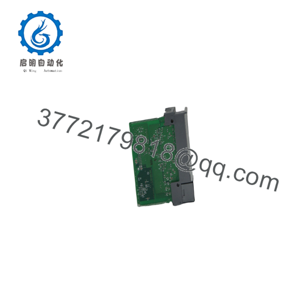
1746-NI4
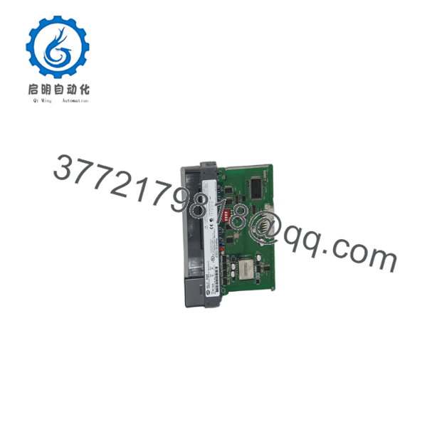
1746-NI4
Frequently Asked Questions
Can each input channel be configured independently?
Yes. Each of the four differential channels can be configured for either voltage or current input, allowing mixed analog signal types within the same module.
Is the 1746-NI4 still manufactured?
No. Rockwell Automation discontinued the 1746-NI4 on April 29, 2021. Most available units today are New Surplus or professionally tested refurbished modules.
Will replacing the module affect my PLC program?
No. The PLC application remains stored in the SLC processor. However, you should verify the module configuration and analog scaling after installation to ensure the replacement matches the original hardware configuration.
Why are my analog readings incorrect after replacing the module?
The most common causes are:
- Incorrect voltage/current channel configuration
- Improper jumper or DIP switch settings
- Wiring polarity errors
- Incorrect engineering-unit scaling
- Ground loop or shielding problems
In many cases, the module is functioning correctly and the issue is configuration rather than hardware failure.
Can this module measure both voltage and current simultaneously?
Yes. The module supports mixed applications because each channel is individually configurable for voltage or current input. Verify the configuration before applying field power.
What should I verify before ordering?
Confirm the following:
- Exact catalog number (1746-NI4)
- SLC 500 chassis compatibility
- Required input signal type (±10 V or 0/4–20 mA)
- Existing channel configuration
- Available chassis slot
- Terminal block condition
Taking a few minutes to verify these items before installation can prevent unnecessary commissioning delays and reduce troubleshooting time.



