
 WhatsApp: +86 16626708626
 Email:
  Phone: +86 16626708626
Description
Key Technical Specifications
| Parameter | Specification |
| Module Type | High-Resolution Analog Input Module |
| Number of Channels | 8 software-configurable channels |
| Voltage Input Ranges | \pm 10 V DC, 0 to 10 V DC, 0 to 5 V DC, 1 to 5 V DC |
| Current Input Ranges | 0 to 20 mA, 4 to 20 mA, \pm 20 mA |
| A/D Conversion Resolution | 16-bit |
| Backplane Current (5 V DC) | 200 mA |
| Backplane Current (24 V DC) | 100 mA |
| Conversion Time | 1.2 ms per channel (dependent on filter frequency selection) |
| Channel Isolation | 500 V DC channel-to-backplane and channel-to-chassis isolation |
| Input Impedance | Voltage: 1 M\Omega | Current: 250 \Omeg |
Product Introduction & Supply Chain Strategy
The Allen-Bradley 1746-NI8 is an 8-channel high-resolution analog input module designed for the SLC 500 control platform. It converts continuous current or voltage signals from pressure transducers, flow meters, level sensors, and temperature transmitters into 16-bit digital values for CPU process evaluation.
Because Rockwell Automation has officially retired the SLC 500 family, stocking uncommissioned New Surplus 1746-NI8 units prevents unscheduled shutdowns on high-value continuous process lines. Sourcing genuine New Surplus ensures factory-fresh internal reference voltage circuits and zero capacitor degradation, avoiding the measurement drift, channel noise, and calibration failures typical of second-hand pull-outs.
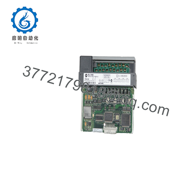
1746-NI8
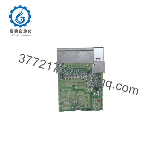
1746-NI8
Installation & Configuration Guide
Stage 1: Pre-Installation (Prep & Safety)
- Perform Lock-Out/Tag-Out (LOTO) procedures on the 1746 chassis power supply and field sensor loop power supplies.
- Put on an ESD-grounded wrist strap attached to cabinet earth ground.
- Record hardware jumper configurations (voltage vs. current mode per channel) and document signal wiring polarities using reference photos.
Stage 2: Removal
- Unfasten the retaining screws on the removable terminal block (RTB) and carefully disconnect it from the front of the 1746-NI8.
- Depress the top and bottom module release latches on the SLC 500 chassis simultaneously.
- Slide the card straight out of the slot along its guide tracks to protect the rear backplane pins from bending or stress.
Stage 3: Installation (Clone & Seat)
- Configure the channel selection jumpers on the replacement 1746-NI8 board to match the input types (Current or Voltage) of the removed card precisely.
- Align the module circuit board with the top and bottom guides of the designated 1746 chassis slot.
- Push the module firmly into the slot until both upper and lower retaining latches snap into place.
- Align the pre-wired RTB onto the terminal header and tighten the retaining screws to 0.5 N·m (4.4 lb·in).
Stage 4: Power-On & Testing
- Verify field signal loops and ensure shield wires are grounded at a single point to prevent ground loops.
- Apply power to the 1746 chassis and monitor the front status LEDs:
- MODULE STATUS: Solid green indicates successful POST diagnostic tests.
- CHANNEL STATUS (0–7): Green indicates valid channel conversion; flashing red indicates an out-of-range signal or open loop.
- Connect using RSLogix 500, verify module Class 1 or Class 3 configuration data words, and monitor input data registers (
I:e.0throughI:e.7) to confirm accurate live process values.
Firmware/Software Versions & Upgrade Notes
- Class Configuration: The 1746-NI8 can operate in Class 1 (standard 8-word input/output) or Class 3 mode (extended diagnostic data). Ensure the I/O configuration in RSLogix 500 matches the physical module series and slot configuration.
- Filter Frequency Selection: Filter settings (e.g., 10 Hz vs. 250 Hz) are configured via software write words. Ensure your ladder logic transfers the correct configuration block to the module on system boot.
- Firmware Notes: Analog I/O modules contain factory-calibrated EEPROM settings and do not support field firmware flashes. Always replace units with identical Series designation (Series A or Series B) to preserve scaling definitions without modifying PLC program code.
Frequently Asked Questions (FAQ)
Q: Is this 1746-NI8 module a Brand New Surplus unit or a refurbished card?
A: This product is a Brand New Surplus unit. It is not used, not pulled from a decommissioned plant, and not refurbished. All modules undergo rigorous quality verification to ensure OEM-level reliability.
Q: Why shouldn’t I buy a cheaper refurbished 1746-NI8 for my plant?
A: High-resolution 16-bit analog cards depend on precise onboard voltage references and filtering capacitors. Refurbished units frequently exhibit signal drift, channel-to-channel crosstalk, or component aging caused by years of thermal exposure. Investing in New Surplus guarantees 10 to 15 years of factory-accurate operation and prevents process trips that can cost tens of thousands in lost production.
Q: How do you verify the authenticity and condition of legacy 1746-NI8 stock?
A: Every unit passes through our inbound SOP quality checks: verifying original OEM anti-static packaging, inspecting backplane edge connectors for zero insertion wear, verifying DIP/jumper integrity, and conducting live 24 V DC signal injection tests on an SLC 500 test chassis.
Q: Do I need to set physical jumpers on the 1746-NI8 for 4–20 mA current loops?
A: Yes. Each channel features individual hardware DIP switches or jumpers on the internal circuit board to toggle between voltage and current modes. You must set these physical jumpers to match your field device outputs before installing the module into the rack.
Q: Is it safe to hot-swap the 1746-NI8 module while the rack is powered up?
A: No. Allen-Bradley SLC 500 chassis backplanes do not support Hot-Swapping (RIUP). Inserting or pulling any 1746 card while backplane power is active causes electrical arcing that can destroy the module, adjacent I/O cards, or the main CPU. Always disconnect chassis power first.
Q: What warranty coverage applies to this New Surplus module?
A: All 1746-NI8 New Surplus cards carry our comprehensive 1-year replacement warranty. If any channel or internal component fails under standard operating conditions, we will provide an advance replacement or issue a full refund immediately.



