
 WhatsApp: +86 16626708626
 Email:
  Phone: +86 16626708626
Description
Key Technical Specifications
| Parameter | Value |
|---|---|
| Product Type | SLC 500 Chassis Power Supply Module |
| Manufacturer | Allen-Bradley / Rockwell Automation |
| Model Number | 1746-P2 |
| Input Voltage | 120/240 V AC nominal |
| Input Frequency | 47–63 Hz |
| Backplane Power Capacity | 149 W |
| 5 V DC Backplane Output | 5 V DC, 5.0 A |
| 24 V DC User Power Output | 24 V DC, 0.96 A |
| Operating Temperature | 0 to 60 °C |
| Storage Temperature | −40 to 85 °C |
| Relative Humidity | 5–95% non-condensing |
| Mounting Type | SLC 500 chassis installation |
| Communication Protocol | Not applicable (power module only) |
Product Introduction
The Allen-Bradley 1746-P2 is an SLC 500 power supply module designed to provide regulated DC power for SLC 500 processor chassis and installed I/O modules. It accepts 120/240 V AC input and supplies 5 V DC backplane power with additional 24 V DC user power output for control applications.
In field maintenance work on SLC 500 systems, the 1746-P2 is commonly replaced when rack power capacity, aging components, or unexpected voltage faults affect PLC availability. Verify chassis loading calculations and existing power requirements before installation.
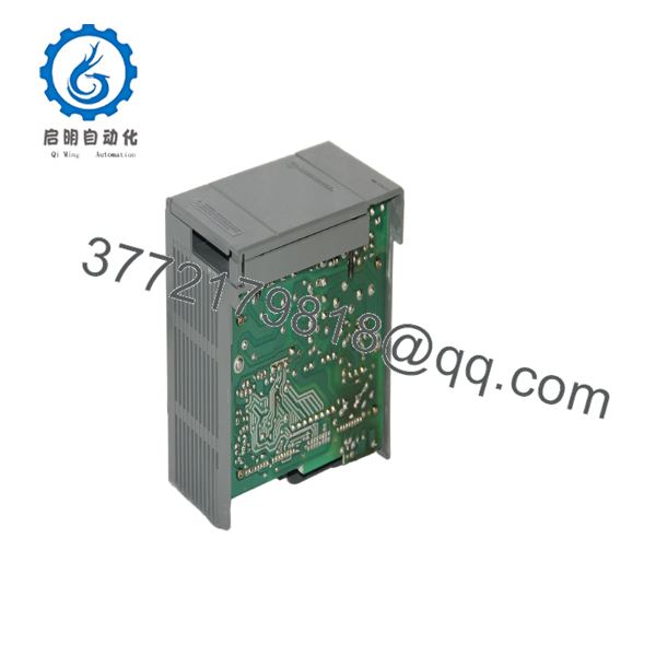
1746-P2
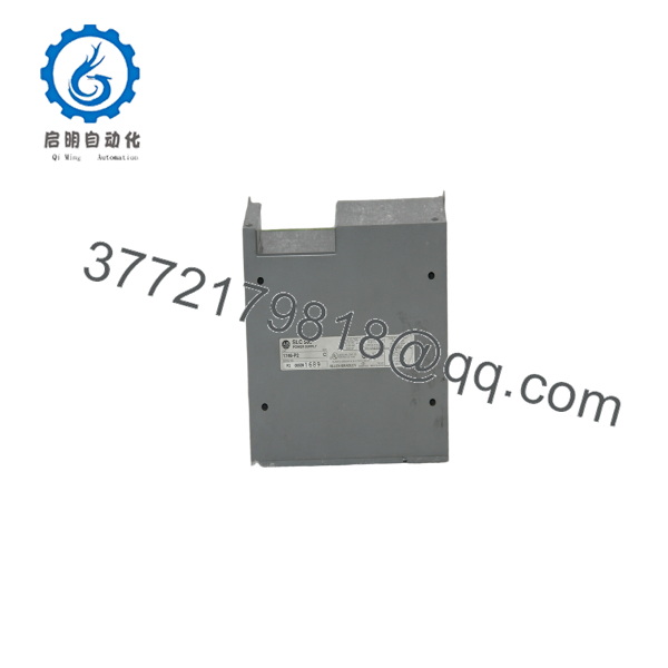
1746-P2
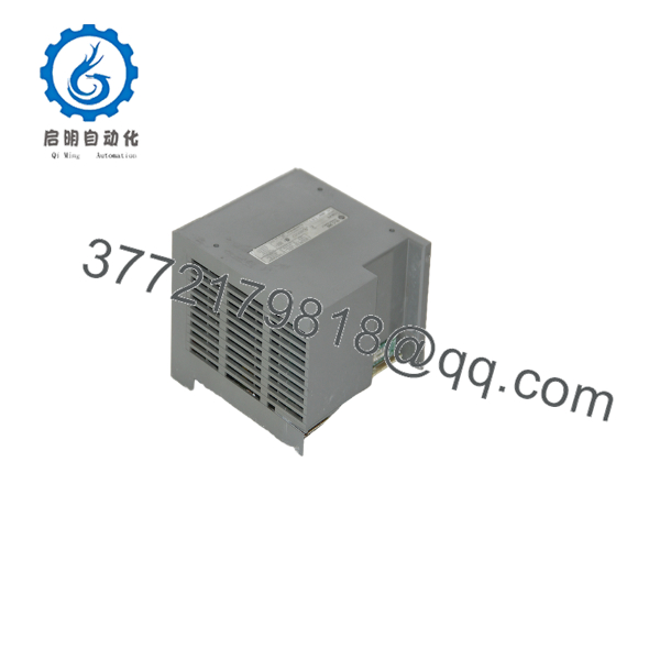
1746-P2
Installation & Configuration Guide
Stage 1: Pre-Installation Preparation (Estimated Time: 10 Minutes)
⚠️ Safety First
- Notify operations personnel before removing the existing power supply.
- Place the controlled process into a safe operating condition.
- Apply lockout/tagout procedures to the AC supply feeding the PLC rack.
- Wait at least 5 minutes after power removal to allow internal capacitors to discharge.
Tools Required
- ESD wrist strap
- PH1 screwdriver
- Digital multimeter
- Wire labels
- Smartphone or camera for reference photos
Data Backup
- Record the existing chassis configuration.
- Photograph the incoming AC wiring and terminal locations.
- Document the SLC 500 processor and I/O module arrangement.
- Verify total rack power consumption before replacement.
⚠️ Important: The 1746-P2 is not a controller module. Removing it does not erase CPU user memory, but an unexpected power interruption can affect volatile data depending on the processor configuration.
Stage 2: Removing the Old Module (Estimated Time: 10 Minutes)
- Remove the protective terminal cover.
- Verify power is fully isolated with a multimeter.
- Label each incoming power wire before disconnecting.
- Loosen terminal screws and remove wiring carefully.
- Release the chassis locking mechanism.
- Pull the power supply straight away from the chassis connector.
- Inspect the backplane connector for:
- Bent pins
- Dust contamination
- Oxidation marks
- Mechanical damage
⚠️ Note: Keep the removed 1746-P2 available until the replacement unit completes testing. The old module provides a reference for wiring and configuration verification.
Stage 3: Installing the New Module (Estimated Time: 10 Minutes)
- Wear an ESD wrist strap before handling the replacement module.
- Verify the label matches Allen-Bradley 1746-P2.
- Inspect the connector and chassis slot before insertion.
- Align the module with the SLC 500 chassis guide rails.
- Push the module firmly until it seats completely.
- Secure the locking tabs.
- Reconnect AC input wiring using the original terminal layout.
- Tighten terminals according to the manufacturer torque specification.
Self-Checklist
- Correct 1746-P2 model installed
- AC wiring matches original configuration
- Module fully seated
- Terminal screws tightened
- Chassis locking tabs secured
Stage 4: Power-On & Testing (Estimated Time: 15 Minutes)
Pre-Power Check
- Measure the AC supply voltage before energizing.
- Check for wiring shorts between power terminals.
- Confirm chassis grounding.
Power-On Steps
- Energize the PLC rack power supply.
- Observe module status indicators.
- Verify the processor enters normal RUN or REM mode.
- Check processor fault registers.
- Confirm all installed I/O modules communicate correctly.
- Perform a controlled I/O verification test.
⚠️ Troubleshooting Note
- If the processor remains faulted, verify the rack power output and chassis load.
- If multiple I/O modules fail simultaneously, check the 5 V DC backplane supply.
- If the supply trips immediately, disconnect external loads and inspect for wiring faults.
Frequently Asked Questions (FAQ)
Q1: Can the Allen-Bradley 1746-P2 be hot-swapped under power?
No. The 1746-P2 is not designed for hot swapping. Remove AC power before replacement. Pulling the power supply while energized can damage the chassis connector and create a safety risk.
Q2: Is the Allen-Bradley 1746-P2 obsolete?
Yes. The SLC 500 platform is a legacy Allen-Bradley control family. The 1746-P2 is no longer part of current Rockwell Automation production lines, but units remain available through surplus and industrial spare parts channels.
Q3: Is this a genuine new unit or refurbished?
Availability depends on inventory condition. A New Original / New Surplus 1746-P2 should retain original manufacturer labeling and show no signs of installation. Refurbished units should be clearly identified and tested before shipment.
Q4: Will replacing the 1746-P2 erase my PLC program?
No. The user program is stored in the SLC processor, not inside the power supply. However, always verify controller status after power restoration because power loss can affect process values, timers, counters, and data registers depending on the application design.
Q5: What is the replacement option if the 1746-P2 is unavailable?
The correct replacement depends on the SLC 500 chassis configuration and power requirements. Do not select a substitute only by physical fit. Verify:
- Chassis type
- Total backplane current demand
- Required 24 V DC user power output
- Processor and I/O module combination
Q6: Why is the 1746-P2 available below original OEM pricing?
Legacy automation hardware often trades below original catalog pricing because it comes from surplus inventories, plant closures, or discontinued system upgrades. Price differences usually reflect lifecycle status rather than reduced technical capability. Always confirm condition, test records, and warranty terms before purchase.
Q7: What checks should I perform before installing a replacement 1746-P2?
Verify the exact part number, inspect the chassis connector, confirm incoming voltage, and calculate rack power demand. A power supply replacement is straightforward, but incorrect voltage selection or overloaded chassis calculations can cause repeat failures.



