
 WhatsApp: +86 16626708626
 Email:
  Phone: +86 16626708626
Description
Key Technical Specifications
| Parameter | Value |
|---|---|
| Product Type | DH-485/DF1 Communication Interface Module |
| Manufacturer | Allen-Bradley / Rockwell Automation |
| Model Number | 1747-KE |
| Compatible Platform | SLC 500 |
| Primary Function | DH-485 to DF1 communication bridge |
| Communication Ports | CONFIG, DF1, DH-485 |
| Serial Standards | RS-232, RS-422, RS-423, RS-485 |
| Supported Baud Rates | 300 to 19,200 bps |
| Backplane Current | 150 mA @ 5 V DC |
| Backplane Current | 40 mA @ 24 V DC |
| Port Isolation | 500 V DC (CONFIG and DF1 ports) |
| Operating Temperature | 0 to 60 °C |
| Weight | Approximately 168 g (0.37 lb) |
Product Introduction
The Allen-Bradley 1747-KE is a communication interface module for the SLC 500 platform. It acts as a bridge between DH-485 networks and serial devices using the DF1 protocol, allowing remote programming, troubleshooting, and data collection through standard serial communication.
In legacy SLC 500 installations, the 1747-KE remains useful where modern Ethernet connectivity is unavailable. It supports multiple serial standards and enables reliable communication with PLC processors, modems, HMIs, and supervisory computers without replacing the existing control system.
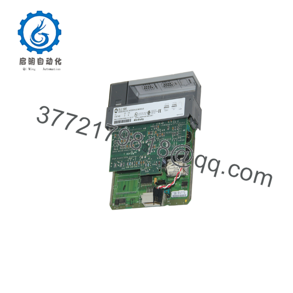
1747-KE
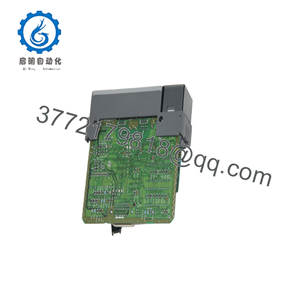
1747-KE
Installation & Configuration Guide
Stage 1 – Pre-Installation Preparation (Estimated Time: 10 Minutes)
⚠️ Safety First
- Notify operations before taking the controller offline.
- Bring the controlled equipment to a safe state.
- Apply lockout/tagout procedures.
- Remove chassis power and wait at least 5 minutes.
Tools Required
- Grounded ESD wrist strap
- PH1 screwdriver
- Fluke 115 digital multimeter
- Wire labels
- Smartphone for recording cable connections
Data Backup
- Back up the SLC 500 project from RSLogix 500.
- Record the DF1 communication settings.
- Document DH-485 node addresses.
- Photograph cable routing and connector locations.
Stage 2 – Removing the Existing Module (Estimated Time: 10 Minutes)
- Verify the chassis is completely de-energized.
- Disconnect all serial communication cables.
- Label every cable before removal.
- Release the retaining tabs.
- Pull the module straight out.
- Inspect the backplane connector for bent pins or contamination.
⚠️ Keep the existing module until the replacement passes all communication tests.
Stage 3 – Installing the Replacement Module (Estimated Time: 10 Minutes)
- Wear an ESD wrist strap.
- Verify the catalog number is 1747-KE.
- Install the module squarely into the chassis.
- Ensure the locking tabs fully engage.
- Reconnect all communication cables.
- Restore DF1 communication parameters and DH-485 addressing.
Self-Checklist
- Correct module installed
- Communication cables secure
- Module fully seated
- Configuration verified
- Node address confirmed
Stage 4 – Power-On & Testing (Estimated Time: 15 Minutes)
Pre-Power Inspection
- Verify 5 V and 24 V backplane capacity.
- Confirm cable integrity.
- Check connector seating.
Commissioning Steps
- Energize the SLC 500 chassis.
- Verify normal module LED operation.
- Connect RSLogix 500 through the DF1 port.
- Confirm communication with the processor.
- Test communication across the DH-485 network.
- Verify remote programming or data transfer functions.
⚠️ Troubleshooting Note
- If the DF1 port does not communicate, verify baud rate, parity, and serial cable type.
- If DH-485 communication fails, verify node addressing and confirm a 1747-AIC Link Coupler is used when connecting to a multi-node DH-485 network. The DH-485 port on the 1747-KE is not isolated and cannot directly drive a multi-node network.
Common Field Pitfalls
❗ Communication Parameter Mismatch
One of the most common service calls involves mismatched DF1 settings. If the baud rate or parity differs from the processor configuration, the module appears dead even though the hardware is operating normally.
❗ Incorrect Cable Selection
The 1747-KE supports multiple serial interfaces. Using an incorrect cable or wiring RS-232 equipment to an RS-485 configuration is a common source of commissioning delays.
❗ DH-485 Network Connections
I’ve seen technicians connect the DH-485 port directly into an existing multi-drop network. It won’t work reliably. For multi-node DH-485 systems, use the specified 1747-AIC Link Coupler. Skipping this requirement often results in intermittent communication faults.
❗ Backplane Power Budget
The module requires both 5 V DC (150 mA) and 24 V DC (40 mA) from the SLC backplane. If a 1747-AIC Link Coupler is powered through the module with the appropriate cable, include that additional current draw in your power calculations. Always leave approximately a 20% margin when sizing the power supply.
❗ Electrostatic Discharge
Communication modules are especially vulnerable to ESD damage around the serial interface circuitry. Always use a grounded wrist strap and handle the board by its edges.
Keep these checks in mind and you’ll avoid most of the communication problems encountered during SLC 500 upgrades.
Frequently Asked Questions (FAQ)
Q1. What does the 1747-KE actually do?
The 1747-KE provides a communication bridge between an SLC 500 DH-485 network and external serial devices using the DF1 protocol. It enables remote programming, diagnostics, modem access, and data acquisition without replacing the existing controller.
Q2. Can I hot-swap the 1747-KE?
No.
The module is not designed for insertion or removal while the chassis is powered. Shut down the PLC, remove power, and follow lockout/tagout procedures before replacing the module.
Q3. Is the 1747-KE obsolete?
Yes.
The 1747-KE belongs to the legacy SLC 500 family. New production has ended, but New Surplus inventory and professionally tested replacement units are still available through industrial automation suppliers.
Q4. Can the 1747-KE connect directly to a multi-node DH-485 network?
Not by itself.
The DH-485 port is not electrically isolated and cannot directly drive a multi-node DH-485 network. Allen-Bradley specifies using a 1747-AIC Link Coupler for these installations.
Q5. Will replacing this module affect my PLC program?
No.
The ladder logic remains stored in the SLC processor. However, communication parameters such as DF1 settings, node addresses, and host configuration should be documented before replacing the module.
Q6. Why are New Surplus units often less expensive than the original OEM price?
Most available units come from unused project inventory, plant expansions, or warehouse surplus after system modernization. Lower pricing generally reflects the product’s lifecycle status rather than reduced functionality. Always request inspection records and functional test results before purchasing.
Q7. What should I verify before commissioning a replacement 1747-KE?
Before placing the system back into service, verify:
- Exact catalog number (1747-KE)
- DF1 communication parameters
- DH-485 node address
- Correct serial cable type
- Backplane power capacity
- Proper use of a 1747-AIC Link Coupler where required
- Successful communication with RSLogix 500 and all connected devices
From field experience, communication settings—not hardware failures—account for the majority of startup delays after replacing a 1747-KE. Spending a few minutes documenting the original configuration usually saves hours of troubleshooting later.



