
 WhatsApp: +86 16626708626
 Email:
  Phone: +86 16626708626
Description
Key Technical Specifications
| Parameter | Specification Value |
| Catalog Number | 1747-L543 |
| Processor Type | SLC 5/04 Controller |
| User Memory Capacity | 64K Words (Data and Program) |
| Communication Ports | Channel 0: RS-232 (DF1, DH-485, ASCII, Modbus RTU Master)
Channel 1: Data Highway Plus (DH+ 3-pin phoenix connector) |
| DH+ Baud Rates | 57.6 kbps, 115.2 kbps, 230.4 kbps |
| Backplane Current (5V DC) | 1.0 A |
| Backplane Current (24V DC) | 200 mA |
| Max Local I/O Capacity | 4,096 Inputs / 4,096 Outputs (max 3 chassis / 30 slots) |
| Program Execution Time | 0.9 ms per 1K instructions (typical) |
| Memory Retention | Lithium Battery (1747-BA) + Optional Flash Memory (1747-M13) |
| Keyswitch Positions | RUN, REM (Remote), PROG (Program) |
| Status Indicators | RUN, FORCE, FLT, DH+, RS232, BATT LEDs |
Product Introduction & Supply Chain Strategy
This product is a Brand New Surplus unit. It is not used, not pulled from a decommissioned plant, and not refurbished. All modules undergo rigorous quality verification to ensure OEM-level reliability. The Allen-Bradley 1747-L543 is a flagship SLC 5/04 processor module equipped with 64K words of configurable memory and an integrated Data Highway Plus (DH+) communication port. Installed in Slot 0 of a 1746 chassis, it provides sub-millisecond execution speeds designed for demanding plant-wide Supervisory Control and Data Acquisition (SCADA) systems, high-speed material handling, and legacy PLC-5 / SLC network integration.
With Rockwell Automation moving the SLC 5/04 line into active-discontinued status, procuring the 1747-L543 as New Surplus is a primary strategic risk-mitigation tool for your facility’s Total Cost of Ownership (TCO). Refurbished processor units carry a high risk of degraded timing crystals, thermal breakdown on internal regulators, and micro-fractured DH+ driver chips that cause sudden intermittent drops across your entire industrial network. Keeping factory-fresh surplus stock on hand guarantees 10-15 years of operational life, prevents costly stock-outs on legacy assembly lines, and avoids immediate capital expenditures required for full PLC platform migrations.
Installation & Configuration Guide
1.Stage 1: Pre-Installation (Prep & Safety):Safeguard program logic, isolate power, and use anti-static protection.
- Perform strict Lock-Out/Tag-Out (LOTO) procedures on the incoming power supply feed for the SLC rack.
- Wear a grounded Electrostatic Discharge (ESD) wrist strap attached to unpainted enclosure frame steel.
- Connect via RSLogix 500 and upload a complete backup copy of the working project file (
.RSS) to your terminal.
2.Stage 2: Removal:Safely disengage the processor module from Slot 0.
- Turn the processor keyswitch to PROG mode.
- Label and disconnect the 3-pin DH+ network terminal block (Clear, Shield, Blue) and the Channel 0 RS-232 serial cable.
- Depress the top and bottom extraction latches on the 1747-L543 casing.
- Pull the module straight out horizontally to avoid stressing or bending the backplane edge connector pins.
3.Stage 3: Installation (Clone & Seat):Install lithium memory battery and seat replacement hardware.
- Attach a fresh 1747-BA lithium battery to the battery lead on the processor board side.
- If utilizing an optional 1747-M13 Flash memory socket module, seat it securely into the onboard socket.
- Align the board with card guide channels in Slot 0 (far-left position next to the power supply).
- Slide the module firmly into the chassis backplane until both retaining tabs snap closed.
- Re-attach the DH+ 3-pin connector block and RS-232 serial cable.
4.Stage 4: Power-On & Testing:Re-energize hardware, confirm status LEDs, and download project logic.
- Re-apply power to the 1746 chassis power supply.
- Verify that the BATT LED remains OFF; if illuminated solid red, replace the lithium memory battery immediately.
- Establish a terminal link via RSLogix 500 through Channel 0 (RS-232) or Channel 1 (DH+ using a 1784-U2DHP converter).
- Download the target
.RSSbinary file, clear active processor fault registers, and switch the key position to RUN.
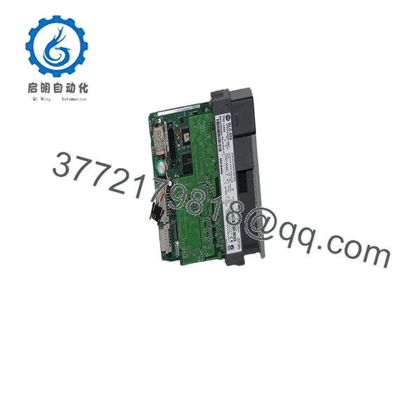
1747-L543
1747-L543
Firmware/Software Versions & Upgrade Notes
- Software Compatibility: Fully supported across RSLogix 500 software versions. Verify that the processor catalog number (1747-L543), hardware Series (Series A, B, or C), and OS revision number in your software project tree match the physical label on the side of the unit.
- DH+ Channel Configuration: Channel 1 hardware defaults to 57.6 kbps. If your plant DH+ trunk line operates at 115.2 kbps or 230.4 kbps, ensure the channel configuration in RSLogix 500 is verified prior to putting the controller online; a baud rate mismatch will isolate the rack from the network.
- Firmware Upgrade Considerations: OS updates on the 1747-L543 are flashable via ControlFLASH or physical OS EEPROM swapping depending on board hardware revision. Flash-updating across an active DH+ network is strongly discouraged due to packet loss risks that can corrupt the bootloader; always flash firmware locally using Channel 0 RS-232.
Frequently Asked Questions (FAQ)
Why is this New Surplus 1747- priced higher than refurbished cards but lower than OEM list?
Our pricing reflects the true cost of acquiring original, unused OEM inventory from global industrial reserves. Refurbished cards are inexpensive because they consist of harvested components exposed to high operational heat and electrical stress. New Surplus provides 100% factory operating life and total peace of mind without the extreme markup of legacy OEM list prices.
Are these 1747- processors genuinely new?
Yes. Every 1747- unit is genuine Allen-Bradley stock, completely unused, with zero backplane terminal wear, clean board traces, and original housing. Packaging is opened only inside certified ESD cleanrooms for visual checks and automated test-rack verification prior to shipment.
What is the difference between the 1747-L541, 1747-L542, and 1747- processors?
The core distinction is user memory capacity within the SLC 5/04 family. The 1747-L541 features 16K words, the 1747-L542 features 32K words, and the 1747- features the maximum 64K words of user instruction and data table memory. All three share identical physical communication ports (DH+ and RS-232).
What causes a red “FLT” LED to flash on the SLC 5/04 front panel?
A flashing red FLT LED indicates a recoverable major fault, such as memory retention loss from a dead battery, an I/O module rack mismatch, an invalid math operation, or an unassigned memory address. Connecting via RSLogix 500 allows you to read the Processor Status file (S:6) to diagnose and clear the specific fault code.
What warranty coverage is included with this New Surplus controller?
We supply a full 1-Year warranty (depending on your selected service tier) covering complete hardware replacement. In the event of any hardware malfunction under normal operating conditions, we immediately dispatch a replacement unit directly from our dedicated buffer stock.



