
 WhatsApp: +86 16626708626
 Email:
  Phone: +86 16626708626
Description
Key Technical Specifications
| Parameter | Value |
|---|---|
| Product Type | Remote I/O (RIO) Scanner Module |
| Manufacturer | Allen-Bradley / Rockwell Automation |
| Model Number | 1747-SN |
| Product Series | SLC 500 |
| Primary Function | Master scanner for Allen-Bradley Remote I/O networks |
| Communication Protocol | Allen-Bradley Remote I/O (RIO) |
| Network Topology | One scanner (master) with multiple remote adapters |
| Supported Logical Racks | Up to 4 logical racks of discrete I/O |
| Block Transfer Support | Up to 64 words (Series B and later) |
| Communication Speeds | 57.6 kbps, 115.2 kbps, 230.4 kbps (DIP switch selectable) |
| Maximum Network Length | Up to 3,048 m (10,000 ft), depending on baud rate |
| Maximum Devices | 16 devices (normal mode), 32 devices (complementary mode) |
| Backplane Current | 600 mA @ 5 V DC |
| Isolation | 500 V DC communication circuit isolation |
| Operating Temperature | 0 to 60 °C |
| Storage Temperature | −40 to 85 °C |
| Relative Humidity | 5–95% non-condensing |
Product Introduction
The Allen-Bradley 1747-SN is a Remote I/O (RIO) Scanner Module designed for SLC 500 processors. It provides the master interface between the PLC and distributed Allen-Bradley Remote I/O devices such as 1746 remote chassis, 1771 I/O, FLEX I/O, PanelView terminals, and other RIO-compatible equipment.
From field experience, the 1747-SN remains common in legacy manufacturing facilities where replacing an entire Remote I/O infrastructure is not economically practical. It allows long-distance distributed I/O while maintaining deterministic communication performance across the RIO network.
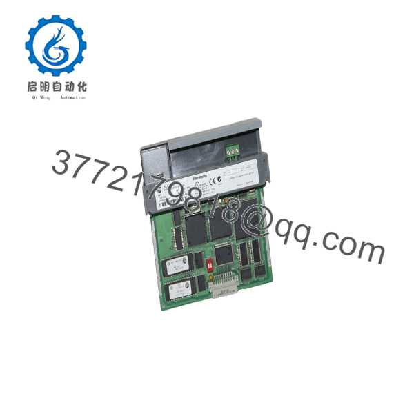
1747-SN
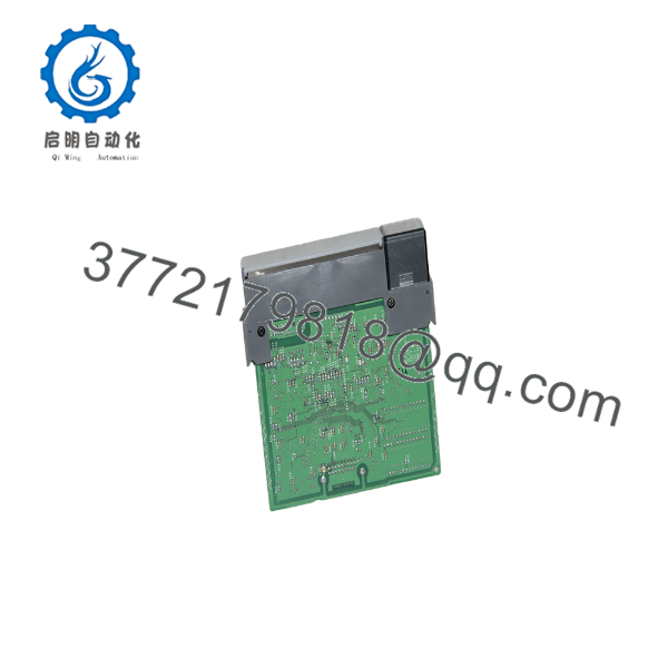
1747-SN
Installation & Configuration Guide
Stage 1 – Pre-Installation Preparation (Estimated Time: 10 Minutes)
⚠️ Safety First
- Notify operations personnel before shutting down the PLC.
- Bring all controlled equipment to a safe operating condition.
- Apply lockout/tagout procedures.
- Remove power from the SLC chassis.
- Wait at least 5 minutes for internal power supplies to discharge.
Tools Required
- Grounded ESD wrist strap
- PH1 screwdriver
- Fluke 115 digital multimeter
- Wire identification labels
- Smartphone for documenting wiring
Data Backup
- Upload the complete RSLogix 500 project.
- Record the Remote I/O scanner configuration.
- Document baud rate and rack addressing.
- Photograph the RIO connector wiring.
- Record DIP switch positions before removal.
Stage 2 – Removing the Existing Module (Estimated Time: 10 Minutes)
- Verify the chassis is completely de-energized.
- Disconnect the RIO communication cable.
- Label every cable before removal.
- Release the module locking tabs.
- Pull the module straight out to protect the backplane connector.
- Inspect the chassis connector for bent pins, oxidation, or contamination.
⚠️ Keep the original scanner until the replacement has completed network testing successfully.
Stage 3 – Installing the Replacement Module (Estimated Time: 10 Minutes)
- Wear a grounded ESD wrist strap.
- Verify the replacement catalog number is 1747-SN.
- Configuration Clone (Critical): Copy every DIP switch position from the original module. This determines communication speed and operating mode.
- Install the module firmly into the chassis until both locking tabs engage.
- Reconnect the RIO communication cable.
- Verify cable shield termination exactly matches the installation manual.
Self-Checklist
- Correct module installed
- DIP switches duplicated
- RIO cable secured
- Module fully seated
- Shield grounding verified
Stage 4 – Power-On & Testing (Estimated Time: 15 Minutes)
Pre-Power Checks
- Measure chassis supply voltage.
- Verify RIO cable continuity.
- Confirm cable shield is grounded only at the scanner end.
Commissioning Procedure
- Energize the SLC chassis.
- Observe the SCANNER and COMM FAULT LEDs.
- Verify the processor recognizes the scanner.
- Confirm all remote adapters establish communication.
- Verify remote I/O image updates.
- Test critical field devices before returning production to service.
⚠️ Troubleshooting Notes
- COMM FAULT LED ON: Verify baud rate and remote rack addressing.
- No remote I/O updates: Inspect blue and clear twisted-pair wiring and network termination.
- Intermittent communication: Check shield grounding. Ground the RIO cable shield at the scanner end only.
Common Field Pitfalls
❗ DIP Switch Configuration
This is the mistake I encounter most often. Someone installs a replacement scanner but leaves the factory DIP switch settings unchanged. The scanner powers up, yet none of the remote racks respond. Photograph every switch before removing the original module.
❗ RIO Cable Shielding
Do not ground the shield at both ends. Ground loops introduce communication noise that produces intermittent faults which are extremely difficult to diagnose. Rockwell specifies grounding the shield only at the scanner end.
❗ Remote Rack Addressing
I’ve seen technicians replace a remote adapter when the real issue was duplicate rack addressing. Verify every rack number before replacing hardware.
❗ Power Supply Capacity
The 1747-SN requires approximately 600 mA at 5 V DC from the SLC backplane. Before adding communication or specialty modules, calculate total chassis loading and maintain at least a 20% reserve capacity.
❗ Electrostatic Discharge
Communication ASICs are sensitive to static electricity. Always use a grounded wrist strap and handle the module by its edges.
Keep these checks in mind and you’ll eliminate most Remote I/O startup problems before production resumes.
Frequently Asked Questions (FAQ)
Q1. Is the Allen-Bradley 1747-SN obsolete?
Yes.
Rockwell Automation discontinued the 1747-SN Remote I/O Scanner Module with an end-of-sale date of March 31, 2024. It remains available through surplus inventory and repair channels for existing SLC 500 installations.
Q2. Can I hot-swap the 1747-SN?
No.
The module is not hot-swappable. Removing or installing it with chassis power applied can interrupt the entire Remote I/O network and may damage the backplane.
Q3. What devices can the 1747-SN communicate with?
The scanner supports Allen-Bradley Remote I/O devices including:
- 1746 Remote I/O chassis
- 1771 I/O systems
- FLEX I/O
- PanelView terminals
- PowerMonitor devices
- Other compatible RIO adapters
It functions as the master device on the RIO network.
Q4. What communication distance is supported?
Depending on the selected baud rate, the RIO network can extend up to 3,048 m (10,000 ft) using approved twisted-pair cable. Lower communication speeds allow longer cable runs.
Q5. Why is a New Surplus unit less expensive than the historical OEM price?
Most New Surplus inventory originates from canceled projects, warehouse stock, or plant modernization programs. The lower price reflects lifecycle status rather than reduced functionality. Always verify the module condition, inspection records, and warranty before purchase.
Q6. How is every 1747-SN inspected before shipment?
Each module should complete a documented inspection procedure:
- Inbound Inspection & Traceability
- Verify serial number and OEM identification.
- Inspect for corrosion, connector wear, rework marks, and UV discoloration.
- Functional Testing
- Install the scanner in a genuine SLC 500 chassis.
- Verify LED startup sequence.
- Establish communication with multiple Remote I/O adapters.
- Perform block transfer verification.
- Operate continuously for more than 24 hours while monitoring communication stability.
- Electrical Testing
- Insulation resistance test using a 500 V Megger.
- Ground continuity verification.
- Communication circuit inspection.
- Configuration Verification
- Record hardware revision.
- Verify DIP switch operation.
- Confirm communication speed selection.
- Final QC & Packaging
- QC approval.
- Anti-static ESD packaging.
- Heavy-duty corrugated shipping carton.
- QC Passed label with inspection date.
Test photographs and operational videos should be available upon request.
Q7. What should I verify before installing a replacement 1747-SN?
Before commissioning, verify:
- Exact catalog number (1747-SN)
- DIP switch settings
- RIO baud rate
- Remote rack addressing
- Cable shield grounding
- Backplane power capacity
- Remote I/O communication status
In practice, most Remote I/O problems are caused by configuration or cabling rather than scanner hardware. Spending a few minutes documenting the original installation usually prevents hours of troubleshooting later.



