
 WhatsApp: +86 16626708626
 Email:
  Phone: +86 16626708626
Description
Key Technical Specifications
| Parameter | Value |
|---|---|
| Product Type | EtherNet/IP Communication Bridge Module |
| Manufacturer | Allen-Bradley / Rockwell Automation |
| Model Number | 1756-EN2TR |
| Product Series | ControlLogix |
| Communication Protocol | EtherNet/IP, CIP, TCP/IP |
| Ethernet Ports | 2 × RJ45 (10/100 Mbps) |
| Network Topology | Linear, Star, Device Level Ring (DLR) |
| Maximum CIP Connections | 256 |
| TCP Connections | 128 |
| CIP Unconnected Messages | 128 (Ethernet) + 128 (Backplane) |
| Current Draw | 1.0 A @ 5.1 V DC, 3 mA @ 24 V DC |
| Power Dissipation | 5.1 W |
| Isolation Voltage | 30 V continuous |
| Mounting | ControlLogix Chassis |
| Operating Temperature | 0 to 60 °C |
| Storage Temperature | −40 to 85 °C |
| Relative Humidity | 5–95% non-condensing |
The 1756-EN2TR is a dual-port EtherNet/IP bridge module that supports Device Level Ring (DLR) redundancy, making it suitable for high-availability ControlLogix architectures.
Product Introduction
The Allen-Bradley 1756-EN2TR is a ControlLogix EtherNet/IP communication module that connects ControlLogix controllers to industrial Ethernet networks. Its dual RJ45 ports support standard star, linear, and Device Level Ring (DLR) topologies while providing deterministic communications for distributed I/O, HMIs, SCADA systems, and peer-to-peer controller messaging.
From field deployments, the 1756-EN2TR is frequently selected for applications requiring network redundancy without installing external managed switches. The integrated DLR capability helps maintain communications during a single network break, reducing unplanned downtime in critical manufacturing systems.
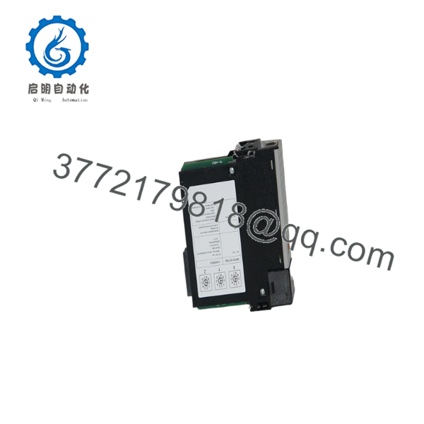
1756-EN2TR
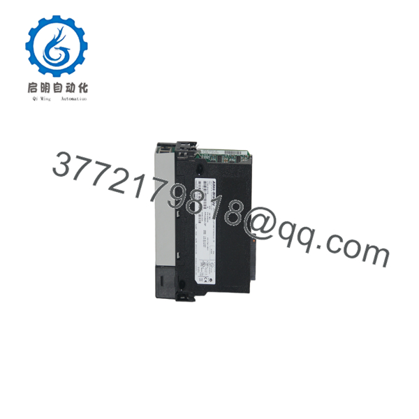
1756-EN2TR
Installation & Configuration Guide
Stage 1 – Pre-Installation Preparation (Estimated Time: 10 Minutes)
⚠️ Safety First
- Notify operations before shutdown.
- Place the process in a safe operating condition.
- Apply lockout/tagout procedures.
- Remove chassis power.
- Wait at least 5 minutes before opening the enclosure.
Tools Required
- Grounded ESD wrist strap
- PH1 screwdriver
- Fluke 115 multimeter
- Torque screwdriver
- Cable labels
- Smartphone for documenting network wiring
Data Backup
- Upload the Studio 5000 project.
- Record the module IP address.
- Save the ACD project.
- Record firmware revision.
- Photograph Ethernet connections.
- Document DLR supervisor configuration if enabled.
Stage 2 – Removing the Existing Module (Estimated Time: 10 Minutes)
- Verify chassis power is OFF.
- Disconnect both Ethernet cables.
- Label every network connection.
- Release the locking tabs.
- Remove the module straight out.
- Inspect the chassis backplane connector.
⚠️ Keep the original module until the replacement has completed commissioning successfully.
Stage 3 – Installing the New Module (Estimated Time: 10 Minutes)
- Wear a grounded ESD wrist strap.
- Verify the catalog number is 1756-EN2TR.
- Install the module completely into the chassis.
- Confirm both locking tabs engage.
- Reconnect Ethernet cables to the documented ports.
- Restore the original IP configuration.
- Verify firmware compatibility if electronic keying is enabled.
Self-Checklist
- Correct model installed
- Module fully seated
- Ethernet cables connected
- IP address verified
- Firmware checked
Stage 4 – Power-On & Testing (Estimated Time: 20 Minutes)
Pre-Power Checks
- Verify chassis power supply capacity.
- Check Ethernet cable integrity.
- Confirm network grounding.
- Inspect RJ45 connectors.
Commissioning Steps
- Apply chassis power.
- Observe OK, NET, and LINK LEDs.
- Connect using Studio 5000.
- Verify module status.
- Confirm EtherNet/IP communication with controllers and I/O.
- Test HMI and SCADA communications.
- Verify DLR ring status if redundancy is configured.
⚠️ Troubleshooting Notes
- NET LED Red: Verify IP conflicts or firmware compatibility.
- No Ethernet communication: Check subnet mask, gateway, switch configuration, and cable integrity.
- DLR Fault: Verify all DLR-capable devices are correctly connected. Standard Ethernet switches do not participate in a DLR ring unless specifically designed for DLR operation.
Common Field Pitfalls
❗ Firmware Revision Mismatch
Electronic keying can reject replacement modules with different firmware revisions. Before removing the original module, document its firmware version and configure compatible keying in Studio 5000.
❗ Device Level Ring Configuration
A common mistake is connecting the 1756-EN2TR through ordinary Ethernet switches while expecting DLR redundancy to function. DLR requires compatible devices throughout the ring. Mixing unsupported switches into the ring breaks redundancy.
❗ IP Address Duplication
I’ve seen maintenance crews install a spare module that retained an old IP address from another project. The module appeared healthy, but duplicate IP addresses disabled communications across multiple controllers. Verify network settings before reconnecting the cables.
❗ Backplane Power Capacity
The module draws approximately 1.0 A at 5.1 V DC. Calculate total chassis current consumption before adding communication modules and maintain at least a 20% reserve.
❗ Electrostatic Discharge
Ethernet interface circuitry is sensitive to static electricity. Handle the module by its edges and always use a grounded wrist strap during installation.
Keep these checks in mind and you’ll avoid most EtherNet/IP commissioning problems before production resumes.
Frequently Asked Questions (FAQ)
Q1. Is the Allen-Bradley 1756- obsolete?
No.
The remains an active Rockwell Automation product with ongoing support, firmware updates, and a standard one-year warranty.
Q2. What is the difference between the 1756-EN2T and 1756-?
The includes dual Ethernet ports with integrated Device Level Ring (DLR) capability, allowing redundant ring topologies. The standard 1756-EN2T provides dual ports but does not provide the same DLR redundancy features.
Q3. Can I hot-swap the 1756-?
ControlLogix systems support Removal and Insertion Under Power (RIUP) for many communication modules. Even so, replacing an active communication module can interrupt EtherNet/IP traffic. Follow your site’s maintenance procedures and verify network recovery before returning the process to production.
Q4. How many EtherNet/IP devices can the module support?
The module supports up to 256 CIP connections and 128 TCP connections, depending on controller resources, firmware revision, and application design. Actual capacity depends on I/O update rates, messaging load, and network architecture.
Q5. Why is a New Surplus module priced below OEM distribution?
New Surplus inventory generally originates from canceled projects, unused maintenance stock, or system upgrades. Lower pricing reflects inventory source and market availability rather than reduced functionality. Always verify serial numbers, hardware revision, inspection records, and warranty coverage before purchase.
Q6. How is each 1756- inspected before shipment?
Every module should complete a documented inspection process:
- Inbound Inspection & Traceability
- Verify OEM labels and serial numbers.
- Inspect connectors, enclosure, and PCB.
- Check for corrosion, scratches, repair marks, and UV discoloration.
- Functional Testing
- Install in a genuine ControlLogix chassis.
- Verify LED startup sequence.
- Test both Ethernet ports.
- Verify EtherNet/IP communications.
- Operate continuously for more than 24 hours under network load.
- Electrical Testing
- Perform insulation resistance testing using a 500 V Megger.
- Verify ground continuity.
- Check communication circuitry.
- Firmware & Configuration Verification
- Record firmware revision.
- Verify hardware revision.
- Confirm DLR operation where applicable.
- Final QC & Packaging
- QC inspector approval.
- Anti-static ESD packaging.
- Heavy-duty corrugated shipping carton.
- QC Passed label with inspection date.
Test reports, photographs, and communication verification videos should be available upon request.
Q7. What should I verify before installing a replacement 1756-?
Before commissioning, verify:
- Exact catalog number ()
- Firmware revision
- IP address and subnet mask
- Electronic keying settings
- Ethernet cable condition
- DLR configuration (if used)
- Chassis power capacity
- Studio 5000 hardware configuration
In field troubleshooting, communication failures are more often caused by IP addressing errors, electronic keying mismatches, or network configuration issues than by a failed EtherNet/IP bridge module. Recording the original settings before replacement typically reduces commissioning time significantly.



