
 WhatsApp: +86 16626708626
 Email:
  Phone: +86 16626708626
Description
Key Technical Specifications
| Parameter | Specification Value |
|---|---|
| Catalog Number | 1756-IB32 |
| Number of Inputs | 32 discrete points (2 groups of 16 channels, shared common per group) |
| Voltage Category | 12/24V DC Sink/Source |
| Operating Voltage Range | 10 to 31.2V DC |
| On-State Current | 2.0 mA min @ 10V DC; 5.5 mA nom @ 24V DC; 13 mA max @ 31.2V DC |
| Off-State Voltage / Current | 5.0V DC max / 1.5 mA max |
| Hardware Delay Time | Off to On: 1 ms max + filter time
On to Off: 1 ms max + filter time |
| Configurable Filter Times | 0 ms, 1 ms, 2 ms, 9 ms, or 18 ms (selectable per point or group) |
| Backplane Current (5.1V DC) | 120 mA |
| Backplane Current (24V DC) | 2 mA |
| Compatible Removable Terminal Block | 1756-TBCH (36-pin Cage Clamp) or 1756-TBS6H (36-pin Spring Clamp) |
Product Introduction & Supply Chain Strategy
This product is a Brand New Surplus unit. It is not used, not pulled from a decommissioned plant, and not refurbished. All modules undergo rigorous quality verification to ensure OEM-level reliability. The Allen-Bradley 1756-IB32 is a high-density 32-channel discrete DC input card designed for ControlLogix chassis. Doubling the point density of standard 16-channel cards allows control system designers to double input capacity without expanding chassis size or adding remote I/O drops.
Sourcing the 1756-IB32 as New Surplus is a practical strategy for maintaining high-density panel footprints while avoiding factory backorders. Refurbished high-density cards frequently carry hidden channel damage from overcurrent faults, cracked 36-pin connector housings, or degraded optical isolators that lead to false signals on neighboring channels. Installing a factory-fresh surplus 1756-IB32 guarantees 100% channel isolation and long-term operational stability for critical process loops.
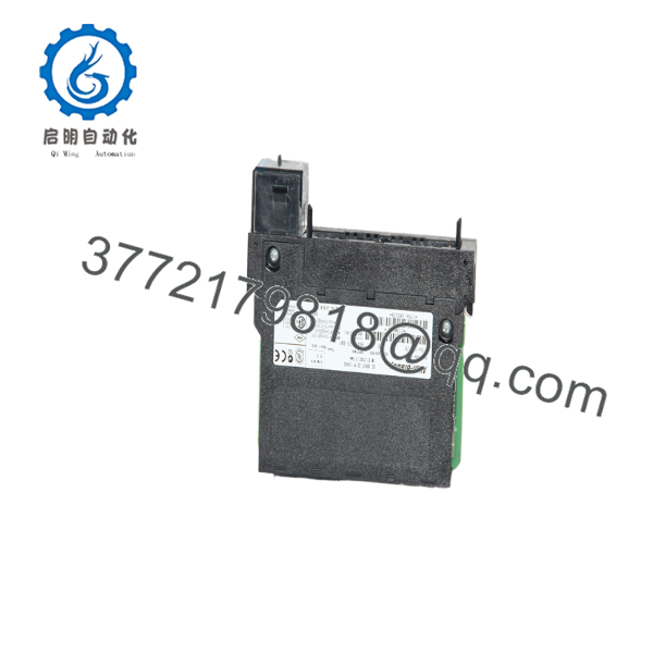
1756-IB32
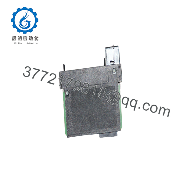
1756-IB32
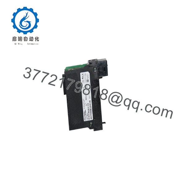
1756-IB32
Installation & Configuration Guide
1
Stage 1: Pre-Installation (Prep & Safety)
Disconnect panel power, wear static protection, and double-check 36-pin RTB pinouts
1.Stage 1: Pre-Installation (Prep & Safety):Disconnect panel power, wear static protection, and double-check 36-pin RTB pinouts.
- Enforce strict Lock-Out/Tag-Out (LOTO) protocols on the field power supply feeding sensors and field switches.
- Wear a grounded Electrostatic Discharge (ESD) wrist strap attached to an unpainted cabinet frame.
- Verify wiring on the 36-pin Removable Terminal Block (1756-TBCH or 1756-TBS6H), paying attention to separate group commons (
IN-COM-0for channels 0–15 andIN-COM-1for channels 16–31).
2
Stage 2: Removal
Unlatch 36-pin RTB and carefully pull the card out of the chassis
2.Stage 2: Removal:Unlatch 36-pin RTB and carefully pull the card out of the chassis.
- Depress the locking tab and pull the 36-pin Removable Terminal Block (RTB) forward to disconnect field wiring harness without disturbing individual wires.
- Squeeze the upper and lower module retention tabs on the 1756-IB32 housing simultaneously.
- Slide the module horizontally straight out of the chassis slot.
3
Stage 3: Installation (Clone & Seat)
Align module rails, seat card into chassis slot, and secure 36-pin RTB
3.Stage 3: Installation (Clone & Seat):Align module rails, seat card into chassis slot, and secure 36-pin RTB.
- Line up the circuit board edges with the top and bottom guide rails inside the target chassis slot.
- Push the module firmly into the rack until both top and bottom latches click into place.
- Snap the wired 36-pin RTB onto the front interface of the module until the locking bar latches fully.
4
Stage 4: Power-On & Testing
Power up system, verify point status LEDs, and test channel tags
4.Stage 4: Power-On & Testing:Power up system, verify point status LEDs, and test channel tags.
- Re-energize the ControlLogix chassis and the external 24V DC sensor supply.
- Check that the module OK LED lights up solid green.
- Trigger field devices across both input banks (0–15 and 16–31) and observe corresponding yellow point status LEDs.
- Connect via Studio 5000 / RSLogix 5000 to verify that all 32 input bits update cleanly in the controller tag array.
Firmware/Software Versions & Upgrade Notes
- Software Compatibility: Compatible with all versions of Studio 5000 Logix Designer and RSLogix 5000.
- Important Terminal Block Difference: The 1756-IB32 requires a 36-pin RTB (1756-TBCH or 1756-TBS6H). It is not compatible with the 20-pin RTBs (1756-TBNH/TBSH) used on the 16-point 1756-IB16 module.
- Group Isolation: The 32 channels are arranged in 2 isolated groups of 16 points each. Group 0 (Points 0–15) and Group 1 (Points 16–31) can be powered by separate 24V DC power supply sources if needed.
Frequently Asked Questions (FAQ)
What is the main difference between the 1756-IB16 and the 1756-?
The 1756-IB16 provides 16 input points and uses a 20-pin terminal block. The 1756- provides 32 input points in the same single chassis slot space, using a 36-pin terminal block (1756-TBCH or 1756-TBS6H) to handle the higher wire density.
Can I mix sinking and sourcing sensors on the same 1756- module?
Yes. Because the 32 points are divided into two independent groups of 16 points (IN-COM-0 and IN-COM-1), you can wire one group for sinking sensors and the second group for sourcing sensors.
Does the 1756- come with the 36-pin terminal block included?
No. Removable Terminal Blocks (RTBs) are separate accessories. If replacing an existing 1756- module, you can re-use your original 1756-TBCH or 1756-TBS6H block without needing to re-wire individual field conductors.
What causes a “Module Fault” indicator in Studio 5000 for this card?
Common triggers include missing backplane communications, Electronic Keying mismatch (e.g., Major/Minor revision mismatch when set to “Exact Match”), or failure to properly seat the module into the backplane connector.
What warranty is included with this New Surplus card?
We provide a comprehensive 1-Year hardware warranty (depending on your service tier). In the event of any hardware failure during standard operation, an immediate replacement unit is dispatched directly from our dedicated buffer stock.



