
 WhatsApp: +86 16626708626
 Email:
  Phone: +86 16626708626
Description
Key Technical Specifications
| Parameter | Specification Value |
|---|---|
| Catalog Number | 1756-IF8 |
| Number of Inputs | 8 single-ended, 4 differential, or 2 high-speed differential channels |
| Input Ranges | Voltage: ±10V, 0 to 10V, 0 to 5V
Current: 0 to 20 mA (requires 249 Ω precision shunt resistor across terminals) |
| Resolution | 16 bits across range (e.g., ~320 µV/bit @ ±10V, ~0.65 µA/bit @ 0–20 mA) |
| Input Impedance | Voltage mode: >10 MΩ
Current mode: 249 Ω (with external resistor) |
| Module Scan Time | 16 ms (single-ended) / 8 ms (differential) / 5 ms (high-speed differential) |
| Backplane Current (5.1V DC) | 150 mA |
| Backplane Current (24V DC) | 65 mA |
| Power Dissipation | 1.73 W max |
| Compatible Removable Terminal Block | 1756-TBNH (20-pin NEMA) or 1756-TBSH (20-pin Spring Clamp) |
Product Introduction & Supply Chain Strategy
This product is a Brand New Surplus unit. It is not used, not pulled from a decommissioned plant, and not refurbished. All modules undergo rigorous quality verification to ensure OEM-level reliability. The Allen-Bradley 1756-IF8 is the primary 8-channel analog input module for ControlLogix automation platforms. It interfaces directly with process transmitters, temperature transmitters, pressure sensors, and variable speed drive speed feedbacks operating on standard 4–20 mA or 0–10V analog signals.
Sourcing the 1756-IF8 as New Surplus is a high-value risk mitigation strategy for your plant’s instrumentation infrastructure. Refurbished or used analog cards frequently suffer from drifted ADC calibration, degraded signal filtering capacitors, or damaged channel inputs from field overvoltage surges. Installing a factory-fresh surplus unit guarantees original 16-bit analog-to-digital converter accuracy, proper onboard signal isolation, and reliable readings across all process control loops.
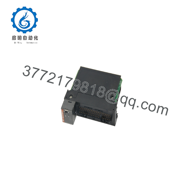
1756-IF8
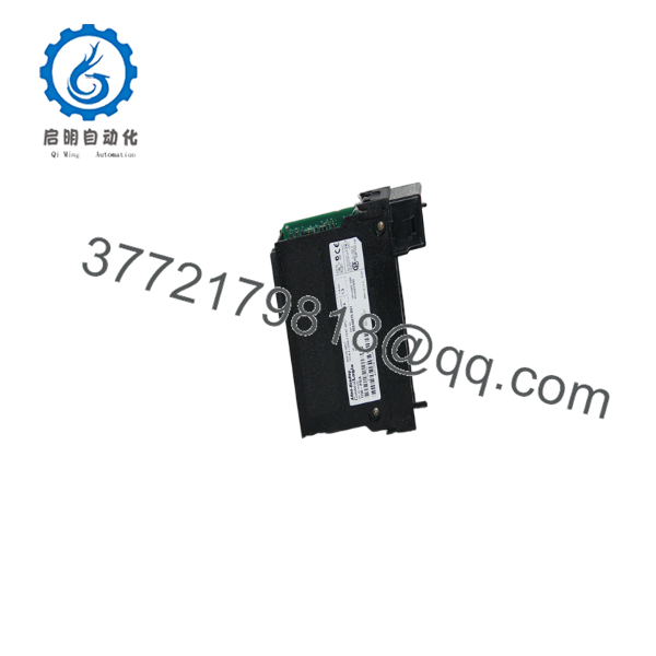
1756-IF8
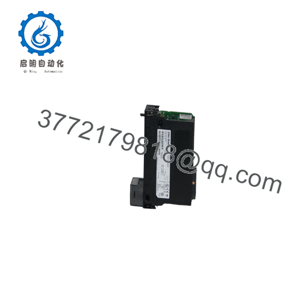
1756-IF8
Installation & Configuration Guide
1
Stage 1: Pre-Installation (Prep & Safety)
Enforce safety protocols, ESD protection, and configure signal mode jumpers/resistors
1.Stage 1: Pre-Installation (Prep & Safety):Enforce safety protocols, ESD protection, and configure signal mode jumpers/resistors.
- Execute strict Lock-Out/Tag-Out (LOTO) procedures on the power supply feeding the field instrumentation loop.
- Wear a grounded Electrostatic Discharge (ESD) wrist strap attached to an unpainted metal surface on the enclosure.
- Determine whether channels are operating in Voltage or Current mode. If configuring for 0–20 mA / 4–20 mA current loops, install 249 Ω shunt resistors across the input terminals on the 20-pin Removable Terminal Block (1756-TBNH or 1756-TBSH).
2
Stage 2: Removal
Unlatch terminal block and safely extract the old module
2.Stage 2: Removal:Unlatch terminal block and safely extract the old module.
- Unlatch and pull the Removable Terminal Block (RTB) forward to disconnect field wiring without disturbing individual conductors.
- Simultaneously depress the top and bottom module retention latches on the 1756-IF8 faceplate.
- Slide the module horizontally straight out of the ControlLogix chassis slot.
3
Stage 3: Installation (Clone & Seat)
Align chassis guide rails, seat the card, and lock the RTB in place
3.Stage 3: Installation (Clone & Seat):Align chassis guide rails, seat the card, and lock the RTB in place.
- Align the top and bottom edges of the replacement 1756-IF8 circuit board with the chassis guide rails.
- Push the module firmly into the slot until both top and bottom latches snap into place.
- Re-attach the pre-wired 20-pin RTB onto the front interface of the module and lock the latching bar.
4
Stage 4: Power-On & Testing
Re-apply power, monitor diagnostic LEDs, and calibrate tag scaling in Studio 5000
4.Stage 4: Power-On & Testing:Re-apply power, monitor diagnostic LEDs, and calibrate tag scaling in Studio 5000.
- Re-apply power to the ControlLogix chassis and field instrument loops.
- Confirm that the OK LED on the module front panel illuminates solid green.
- Open Studio 5000 / RSLogix 5000 and verify channel configuration settings (High/Low Engineering Units, Filter Frequencies, Alarm Limits).
- Inject known 4 mA and 20 mA signals across input channels to verify live data values in the controller tag database.
Firmware/Software Versions & Upgrade Notes
- Software Compatibility: Fully supported across all versions of Studio 5000 Logix Designer and RSLogix 5000.
- Single-Ended vs. Differential Mode: Channel wiring and configuration in Studio 5000 must match. Single-Ended mode offers up to 8 channels sharing a common return line, whereas Differential mode offers up to 4 independent channels for higher noise rejection.
- Onboard Signal Filtering & Alarms: Each channel supports configurable low-pass digital filtering (10 Hz, 50 Hz, 60 Hz, or 1000 Hz notch filters) and programmable Process/Rate-of-Change alarms directly in the module properties dialog.
Frequently Asked Questions (FAQ)
What is the difference between the 1756-IF8 and the 1756-IF8I (Isolating) module?
- 1756-IF8: Non-isolated analog module (channels share a common ground reference in single-ended mode).
- 1756-IF8I: Individually Isolated analog module where every channel is isolated from channel-to-channel and channel-to-ground, preventing ground loops in complex process installations.
How do I configure a channel on the 1756-IF8 for 4–20 mA current signals?
Because the 1756-IF8 natively measures voltage, measuring a 4–20 mA current loop requires placing a precision 249 Ω shunt resistor across the positive and negative terminals of the channel on the terminal block. In Studio 5000 Module Properties, select “0–20 mA” as the input range and scale the engineering units accordingly (e.g., Low Limit = 4 mA, High Limit = 20 mA).
Does the 1756-IF8 module come with the 20-pin terminal block included?
No. Removable Terminal Blocks (1756-TBNH or 1756-TBSH) and shunt resistors are sold separately by Allen-Bradley. If you are swapping an existing 1756-IF8 card, you can snap your original RTB (complete with existing shunt resistors and wiring) directly onto the new surplus module.
What causes a “Channel Fault” or “Out of Range” LED indicator on this module?
Common causes include an open loop on a 4–20 mA signal wire (current dropping below 2 mA / 0V), an over-range voltage exceeding +10.5V DC, or an uncalibrated input scale configuration in Studio 5000.
What warranty coverage is included with this New Surplus module?
We back every 1756-IF8 unit with a comprehensive 1-Year hardware replacement warranty (depending on your service agreement tier). If any channel or internal component experiences a failure during standard operation, an immediate replacement unit is dispatched directly from our buffer stock.



