
 WhatsApp: +86 16626708626
 Email:
  Phone: +86 16626708626
Description
Key Technical Specifications
| Parameter | Specification Value |
| Catalog Number | 1756-L73 |
| User Data & Logic Memory | 8 MB |
| Non-Volatile Memory | Ships with 1 GB SD card (1784-SD1); supports up to 2 GB (1784-SD2) |
| Processor Family | ControlLogix 5573 |
| Communication Port | USB 2.0 Full Speed (12 Mbps, programming/commissioning port) |
| Energy Storage Module | Uses capacitor-based ESM (1756-ESMCAP or 1756-ESMNSE) instead of lithium batteries |
| Maximum Digital I/O | 128,000 inputs/outputs total |
| Maximum Analog I/O | 4,000 inputs/outputs total |
| Maximum Tasks | 32 tasks (1 continuous task + up to 31 periodic/event tasks) |
| Backplane Current (5.1V DC) | 800 mA |
| Backplane Current (24V DC) | 5 mA |
| Power Dissipation | 2.5 W max |
Product Introduction & Supply Chain Strategy
This product is a Brand New Surplus unit. It is not used, not pulled from a decommissioned plant, and not refurbished. All modules undergo rigorous quality verification to ensure OEM-level reliability. The Allen-Bradley 1756-L73 is an 8 MB controller in the ControlLogix 5570 (L7x) family, delivering four times the user memory of the entry-level 1756-L71. Engineered for demanding industrial environments, the L73 replaces failure-prone lithium backup batteries with a maintenance-free capacitor Energy Storage Module (ESM) that automatically writes RAM data to an internal SD card during unexpected shutdown events.
Sourcing the 1756-L73 as New Surplus provides an ideal solution for plant engineers managing memory-intensive applications or expanding existing 1756 chassis architectures. Upgrading to an L73 from older processors like the 1756-L62 or 1756-L63 delivers a significant leap in execution speed and instruction throughput while preserving compatibility with established 1756 backplanes, I/O modules, and EtherNet/IP networks.
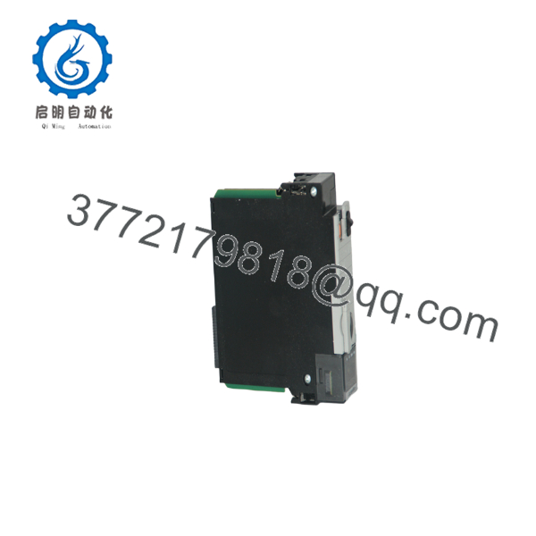
1756-L73
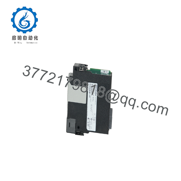
1756-L73
Installation & Configuration Guide
1.Stage 1: Pre-Installation (Prep & Safety):Perform software backup, isolate rack power, and attach ESD wrist strap.
- Upload and verify a complete project backup (
.ACDfile) using Studio 5000 Logix Designer or RSLogix 5000 before removing the existing processor. - Enforce strict Lock-Out/Tag-Out (LOTO) protocols on the ControlLogix chassis power supply.
- Wear a grounded Electrostatic Discharge (ESD) wrist strap connected to an unpainted metal surface on the cabinet frame.
- Ensure that the Energy Storage Module (1756-ESMCAP or 1756-ESMNSE) and SD card (1784-SD1) are firmly seated in the front panel.
2.Stage 2: Removal:Set keyswitch to PROG, disconnect USB cable, and unlatch CPU.
- Turn the physical front-panel keyswitch to the
PROGposition. - Disconnect any USB programming cable from the front port.
- Depress the upper and lower module retention latches on the 1756-L73 housing.
- Slide the controller horizontally straight out of the chassis slot to prevent damage to the backplane connectors.
3.Stage 3: Installation (Clone & Seat):Align guide rails, seat controller, and secure retainers.
- Align the top and bottom edges of the replacement 1756-L73 circuit board with the chassis card guides.
- Push the controller firmly into the slot until both retention latches snap securely into place.
- Connect a USB cable to the front port or establish network communications via adjacent EtherNet/IP bridge modules (e.g., 1756-EN2T/EN3TR).
4.Stage 4: Power-On & Testing:Power up chassis, observe 4-character display, and download project.
- Re-apply power to the ControlLogix chassis power supply.
- Monitor the front 4-character alpha-numeric display and LEDs: confirm that self-diagnostics complete successfully and the display shows the operational state.
- Open Studio 5000 Logix Designer (v20 through current releases), connect via USB or network, match the controller firmware version, and download your project file.
- Turn the keyswitch to
REMorRUNand confirm that all remote I/O chassis, drives, and motion axes go online without faults.
Firmware/Software Versions & Upgrade Notes
- Software Compatibility: Programmed using RSLogix 5000 (v20) and Studio 5000 Logix Designer (v21 through current releases).
- Battery-Free Operation: The 1756-L73 uses a capacitor-based Energy Storage Module (1756-ESMCAP or removable 1756-ESMNSE) to save volatile memory to the non-volatile SD card upon power loss.
- Firmware Flashing: Firmware can be flashed using ControlFLASH or ControlFLASH Plus over the front USB port or through an EtherNet/IP bridge card across the backplane.
- Non-Volatile Storage (SD Card): Includes a 1 GB 1784-SD1 card. Image loading options (Load on Power-Up, Load on Corrupt Memory, User Initiated) are managed in Studio 5000 under Controller Properties -> Non-Volatile Memory.
Frequently Asked Questions (FAQ)
What is the main difference between the 1756-L71, 1756-L72, 1756-L73, and 1756-L74 controllers?
All ControlLogix 5570 controllers share the same CPU architecture, USB port, and ESM backup system. The primary difference is user memory capacity:
- 1756-L71: 2 MB User Memory
- 1756-L72: 4 MB User Memory
- 1756-L73: 8 MB User Memory
- 1756-L74: 16 MB User Memory
Can I replace a 1756-L72 with a 1756-L73 if my program runs out of memory?
Yes. Changing from a 1756-L72 to a 1756-L73 gives you double the memory (8 MB vs. 4 MB). In Studio 5000, simply change the controller type in the project properties to 1756-L73 and re-download. No ladder logic or tag changes are required.
What happens if the Energy Storage Module (ESM) fails or is missing?
If the ESM is missing or damaged, the controller’s front display will generate an ESM fault code. While the processor may continue running on active power, it will be unable to back up RAM to the SD card during a power outage, resulting in memory loss when powered off.
Is the USB port on the 1756-L73 suitable for continuous SCADA/HMI communication?
No. The front USB 2.0 port is designed strictly for local maintenance, programming, and commissioning. Continuous HMI or SCADA monitoring should be handled via dedicated EtherNet/IP modules such as the 1756-EN2T or 1756-EN3TR.
What warranty coverage comes with this New Surplus controller?
We provide a comprehensive 1-Year or 2-Year hardware replacement warranty (depending on your service agreement tier). If any hardware defect occurs under standard operation, an immediate replacement unit is dispatched directly from our buffer stock.



