
 WhatsApp: +86 16626708626
 Email:
  Phone: +86 16626708626
Description
Key Technical Specifications
| Parameter | Value |
|---|---|
| Product Type | Analog Current Output Module |
| Number of Channels | 6 individually isolated outputs |
| Output Signal | 0–21 mA |
| Resolution | 13-bit (2.7 μA) |
| Output Load | 0–1,000 Ω |
| Isolation | 250 V continuous, channel-to-channel and channel-to-backplane |
| Output Accuracy | Better than ±0.1% of range at 25 °C |
| Module Scan Time | 10 ms (integer), 25 ms (floating point) |
| Short Circuit Protection | Electronic current limiting (≤21 mA) |
| Backplane Current | 250 mA @ 5.1 VDC; 225–300 mA @ 24 VDC (load dependent) |
| Mounting | ControlLogix 1756 Chassis |
| Configuration Software | Studio 5000 / RSLogix 5000 |
The 1756-OF6CI is a six-channel isolated analog output module with 0–21 mA outputs, 250 V continuous isolation, and individual channel isolation. Rockwell Automation discontinued the module on December 21, 2016, and classifies it as a legacy product with a functional replacement path.
Product Introduction
The Allen-Bradley 1756-OF6CI is a ControlLogix analog output module designed for applications requiring six independently isolated current outputs. Typical applications include variable speed drives, valve positioners, proportional control valves, and process instrumentation that accept 4–20 mA control signals.
Unlike standard shared-common analog output modules, the 1756-OF6CI isolates every output channel. This minimizes ground loop issues and electrical interference when multiple field devices operate from different power systems. Although discontinued, it remains widely used in legacy ControlLogix installations where maintaining system compatibility is a priority.
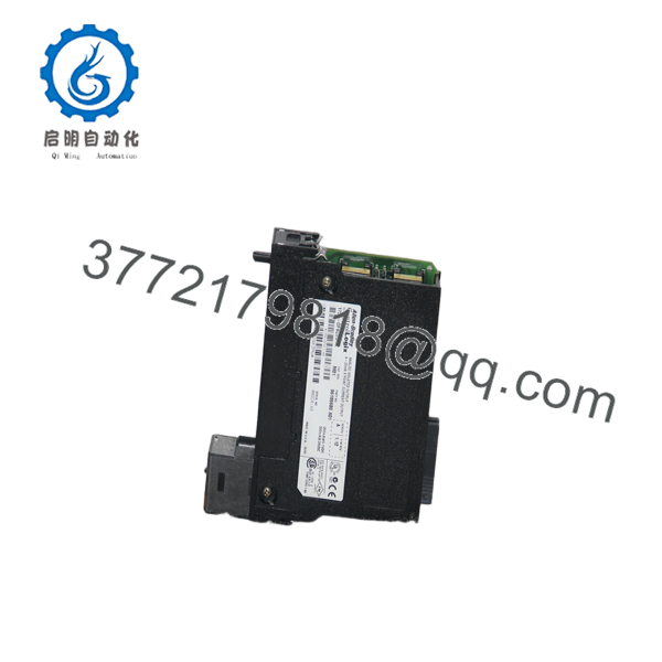
1756-OF6CI
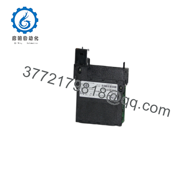
1756-OF6CI
Installation & Configuration Guide
Stage 1 – Pre-Installation Preparation (5–10 minutes)
⚠️ Safety First
- Notify plant operations.
- Perform Lock-Out/Tag-Out.
- Remove system power.
- Wait at least five minutes before opening the cabinet.
Required Tools
- ESD wrist strap
- Digital multimeter
- Phillips screwdriver
- Wire identification labels
- Camera or smartphone
Before Removal
- Upload the Studio 5000 project.
- Record module firmware revision.
- Photograph all terminal wiring.
- Label every analog output loop.
Stage 2 – Remove Existing Module (5 minutes)
- Confirm chassis power is OFF.
- Disconnect the removable terminal block.
- Release the module locking tabs.
- Pull the module straight from the chassis.
- Inspect the backplane connector for contamination or bent pins.
⚠️ Keep the original module until commissioning has been completed successfully.
Stage 3 – Install the New Module (10 minutes)
- Wear an ESD wrist strap.
- Confirm the replacement catalog number is 1756-OF6CI.
- Insert the module completely into the chassis.
- Install the removable terminal block.
- Reconnect each analog output according to the wiring diagram.
- Verify loop resistance does not exceed the specified limit.
Installation Checklist
- ✔ Correct catalog number
- ✔ Wiring verified
- ✔ Module fully seated
- ✔ Terminal block secured
Stage 4 – Power-On & Functional Testing (10–15 minutes)
- Restore chassis power.
- Verify Module OK indicators.
- Confirm the module appears correctly in Studio 5000.
- Verify firmware revision.
- Test each analog output using a loop calibrator or process simulator.
- Confirm field devices respond correctly.
⚠️ Troubleshooting
- Analog output fixed at 0 mA: verify channel configuration.
- Communication fault: confirm electronic keying and firmware compatibility.
- Incorrect output value: inspect load resistance and field wiring.
Frequently Asked Questions
Q1. Is the 1756-OF6CI still manufactured?
No. Rockwell Automation officially discontinued the 1756-OF6CI in December 2016. Most available units today are New Surplus or professionally refurbished.
Q2. What output signals does this module support?
The module provides six individually isolated 0–21 mA analog current outputs, making it suitable for standard 4–20 mA industrial control applications.
Q3. Can I replace the module without changing my PLC program?
Usually yes. If the replacement has the same catalog number and compatible firmware, the controller logic normally remains unchanged. Always verify module profile and electronic keying before returning the system to service.
Q4. Why is individual channel isolation important?
Each channel is electrically isolated from every other channel and from the backplane. This reduces ground loops, minimizes electrical noise, and allows outputs to operate on separate field power systems.
Q5. Is the module hot-swappable?
It is not recommended. Although some ControlLogix systems support online module replacement, shutting down the chassis before replacement is the safest approach and minimizes the risk of equipment damage.
Q6. What should I verify before purchasing a replacement?
Confirm:
- Catalog number ()
- Required firmware revision
- Studio 5000 compatibility
- ControlLogix chassis compatibility
- Required output range (0–21 mA)
- Load resistance requirements
For legacy ControlLogix systems, firmware compatibility is often the most overlooked issue. Document the existing module revision before replacement to reduce commissioning time and avoid unnecessary communication faults.



