
 WhatsApp: +86 16626708626
 Email:
  Phone: +86 16626708626
Description
Key Technical Specifications
| Parameter | Value |
|---|---|
| Product Type | Analog Input Expansion Module |
| Number of Inputs | 4 differential analog inputs |
| Input Signal | ±10 VDC, 4–20 mA |
| Full-Scale Range | ±10.5 VDC, ±21 mA |
| Resolution | 15-bit (bipolar) |
| Input Impedance | 200 kΩ (Voltage), 275 Ω (Current) |
| Bus Current Draw | 40 mA @ 5 VDC, 50 mA @ 24 VDC |
| Update Time | Selectable: 130–530 ms |
| Voltage Protection | ±30 V |
| Current Protection | ±32 mA |
| Mounting | DIN Rail or Panel Mount |
| Compatible Controllers | MicroLogix 1100, 1200, 1400 |
The 1762-IF4 is a four-channel differential analog input module supporting both ±10 VDC and 4–20 mA process signals with 15-bit bipolar resolution. It is compatible with MicroLogix 1100, 1200, and 1400 controllers.
Product Introduction
The Allen-Bradley 1762-IF4 is a compact analog expansion module designed for the MicroLogix controller family. It converts voltage and current signals from transmitters, pressure sensors, flow meters, level instruments, and other process devices into digital data for PLC processing.
Its differential input architecture helps improve measurement stability in electrically noisy industrial environments. The module supports configurable update times, making it suitable for both slow-changing process variables and faster machine monitoring applications.
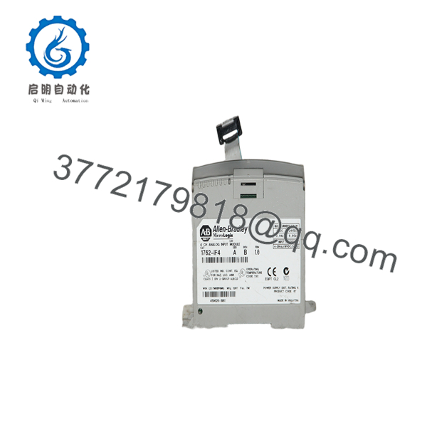
1762-IF4
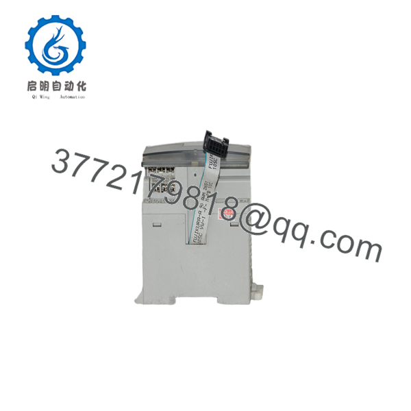
1762-IF4
Installation & Configuration Guide
Stage 1 – Pre-Installation Preparation (5–10 Minutes)
⚠️ Safety First
- Notify operations of the planned maintenance.
- Apply Lock-Out/Tag-Out procedures.
- Remove controller power.
- Wait for all status LEDs to turn off.
Required Tools
- ESD wrist strap
- Digital multimeter
- Small Phillips screwdriver
- Shielded signal cable (Belden 8761 recommended)
- Laptop with RSLogix 500
Before Removal
- Upload the PLC project.
- Record channel configuration.
- Label each analog signal.
- Photograph terminal wiring.
Stage 2 – Remove Existing Module (5 Minutes)
- Verify controller power is OFF.
- Disconnect field wiring.
- Release the expansion module locking tabs.
- Remove the module carefully.
- Inspect expansion bus connectors.
⚠️ Do not force the module from the expansion connector.
Stage 3 – Install the New Module (10 Minutes)
- Verify the replacement is 1762-IF4.
- Install the module onto the expansion bus.
- Secure the locking tabs.
- Reconnect all field wiring.
- Use shielded cable and connect the shield according to Rockwell wiring recommendations.
Installation Checklist
- ✔ Correct model number
- ✔ Differential wiring verified
- ✔ Shield grounding checked
- ✔ Expansion connector fully engaged
Stage 4 – Power-Up & Testing (10–15 Minutes)
- Restore controller power.
- Verify the Module Power LED.
- Open RSLogix 500.
- Configure each channel for Voltage or Current mode.
- Apply a known calibration signal.
- Confirm scaling and engineering units.
⚠️ Troubleshooting
- Unstable readings usually indicate improper shielding or grounding.
- Constant zero input often indicates incorrect channel configuration.
- Over-range alarms typically point to an input signal exceeding the configured range.
Frequently Asked Questions
Q1. What input signals does the 1762-IF4 support?
The module accepts ±10 VDC voltage inputs and 4–20 mA current inputs through four differential channels. It also supports full-scale ranges of ±10.5 VDC and ±21 mA for over-range measurement.
Q2. Which PLCs are compatible?
The 1762-IF4 is compatible with MicroLogix 1100, MicroLogix 1200, and MicroLogix 1400 controllers that support 1762 expansion I/O modules.
Q3. Can one module mix voltage and current inputs?
Yes. Each channel can be configured individually, allowing a combination of voltage and current signals within the same module.
Q4. Why should differential inputs be used?
Differential inputs improve immunity to electrical noise by measuring the voltage difference between two conductors rather than referencing a common ground. This is especially beneficial in industrial environments with long cable runs or variable-frequency drives.
Q5. Is shielded cable recommended?
Yes. Rockwell Automation recommends using Belden 8761 or an equivalent shielded cable for analog signal wiring to minimize electrical interference and improve measurement accuracy.
Q6. What should I verify before ordering?
Confirm the following:
- Catalog number (1762-IF4)
- Number of required analog channels
- Input signal type (Voltage or Current)
- MicroLogix controller compatibility
- Available expansion slot
- Required update time and scaling configuration
One of the most common commissioning mistakes is wiring a 4–20 mA transmitter to a channel configured for voltage input. Before applying power, verify both the field wiring and the software configuration to avoid misleading process values and unnecessary troubleshooting.



