
 WhatsApp: +86 16626708626
 Email:
  Phone: +86 16626708626
Description
Key Technical Specifications
| Parameter | Specification |
|---|---|
| Catalog Number | 1769-IF8 |
| Product Family | Allen-Bradley Compact I/O |
| Module Type | Analog Input |
| Number of Inputs | 8 |
| Input Type | Voltage / Current |
| Voltage Ranges | ±10 V, 0–10 V, 0–5 V, 1–5 V |
| Current Ranges | 0–20 mA, 4–20 mA |
| Resolution | 16-bit |
| A/D Conversion | Delta-sigma |
| Input Configuration | Single-ended or differential |
| Backplane Current | 120 mA @ 5 V DC |
| Maximum Power Dissipation | 2.86 W |
| Operating Temperature | 0 to 60 °C |
| Storage Temperature | -40 to 85 °C |
| Relative Humidity | 5–95%, noncondensing |
| Terminal Block | Removable |
| Wiring | Shielded, twisted-pair analog wiring recommended |
| Isolation | Channel-to-channel non-isolated; system-level isolation per module specification |
The 1769-IF8 provides eight analog inputs and accepts both voltage and current signals. Its configurable ranges make it suitable for transmitters, process sensors, pressure/flow instruments, and other analog field devices connected to CompactLogix or Compact I/O systems.
Product Introduction
The Allen-Bradley 1769-IF8 is an eight-channel analog input module for the 1769 Compact I/O platform. It converts field voltage and current signals into digital values for CompactLogix control applications. Supported input ranges include ±10 V, 0–10 V, 0–5 V, 1–5 V, 0–20 mA, and 4–20 mA.
The module is commonly used for process instrumentation where several analog transmitters must share a compact 1769 I/O system. Channel configuration and scaling must match the actual transmitter range; a 4–20 mA instrument, for example, should not be commissioned using a voltage-input configuration.
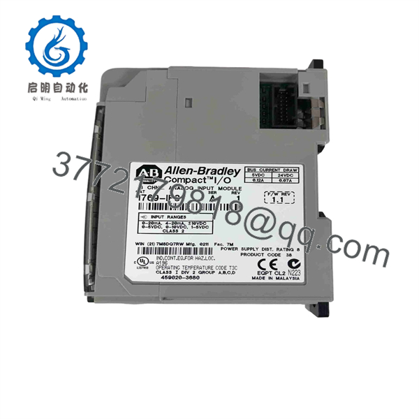
1769-IF8
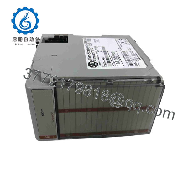
1769-IF8
Installation & Configuration Guide
Stage 1: Pre-Installation Preparation — 10–15 Minutes
⚠️ Safety First: Place the controlled process in a safe state and follow the plant’s electrical isolation/LOTO procedure. Do not disconnect field wiring from an energized analog module unless the applicable Rockwell installation procedure explicitly permits it.
Tools Required:
- ESD wrist strap
- Phillips screwdriver
- Digital multimeter
- Wire labels
- Smartphone/camera
- Laptop with Studio 5000 Logix Designer or applicable programming software
Data Backup:
- Record the existing 1769-IF8 catalog number and Series.
- Identify the CompactLogix controller model.
- Record the module’s physical position in the 1769 assembly.
- Photograph the removable terminal block and every field connection.
- Record each channel’s configured input type and range.
- Back up the controller project.
- Record engineering-unit scaling, alarm limits, and signal-failure handling.
⚠️ Important: The input configuration belongs to the control-system application. Do not assume the replacement module will automatically inherit the correct channel settings.
Stage 2: Removing the Old Module — 5–10 Minutes
- Place the process in the approved maintenance state.
- Isolate power according to the plant procedure.
- Label all field wires before disconnecting them.
- Photograph the terminal block from multiple angles.
- Remove the terminal block using the approved procedure.
- Release the module from the 1769 assembly.
- Pull the module straight out to avoid damaging the bus connector.
- Inspect the adjacent 1769 bus connectors for contamination or damage.
- Keep the old module available until commissioning is complete.
⚠️ Analog wiring warning: Do not trust wire colors alone. Verify each conductor against the electrical drawing and terminal assignment.
Stage 3: Installing the New Module — 5–10 Minutes
- Verify that the replacement is 1769-IF8.
- Compare the Series and physical terminal arrangement with the old unit.
- Inspect the module for cracked housing, corrosion, damaged terminals, or bent contacts.
- Align the module with the 1769 bus connector.
- Push the module into position until fully seated.
- Reinstall the terminal block.
- Reconnect each field conductor according to the wiring photograph and electrical drawing.
- Confirm that shield connections follow the site’s instrumentation grounding standard.
- Secure the module and terminal block.
Self-Checklist:
- Exact 1769-IF8 verified
- Series verified
- Correct module position confirmed
- Terminal block seated
- Field wiring matched
- Shielding/grounding checked
- No loose conductors
Stage 4: Power-On & Testing — 15–30 Minutes
- Perform a visual inspection before energizing.
- Check the analog supply and field wiring for accidental shorts.
- Restore power.
- Verify the module status indication.
- Connect to the CompactLogix controller.
- Confirm that the controller recognizes the module.
- Verify each channel’s configured range.
- Apply a known test signal where practical.
- Compare the raw input value against the reference instrument.
- Verify engineering-unit scaling in the PLC.
- Test high/low alarms and signal-loss behavior.
- Return the process to normal operation after the complete signal path passes testing.
Common Replacement Pitfalls
❗ 1. Wrong Input Range
A 4–20 mA transmitter configured as a voltage input will not produce a meaningful process value. Check the transmitter output type first, then configure the corresponding 1769-IF8 channel.
❗ 2. Wiring the Channel Incorrectly
Analog inputs are sensitive to wiring and grounding arrangements. I’ve seen perfectly good input modules blamed for unstable readings when the actual problem was a shield connected incorrectly at multiple points.
❗ 3. Forgetting Scaling
The raw analog value is not necessarily the engineering-unit value displayed by the HMI. Verify the complete conversion from raw counts to °C, bar, psi, %, flow rate, or the applicable process unit.
❗ 4. Ground Loops
A 4–20 mA loop can behave differently depending on transmitter power architecture and grounding. If the reading fluctuates after replacement, measure the actual loop current rather than immediately replacing the module again.
❗ 5. Reusing Damaged Terminal Blocks
The removable terminal block is part of the physical connection system. Check screw terminals, wire clamps, and connector contacts before transferring it to the replacement module.
Frequently Asked Questions (FAQ)
1. What is the Allen-Bradley 1769-IF8 used for?
The 1769-IF8 is an 8-channel analog input module used with the Allen-Bradley 1769 Compact I/O platform. It accepts voltage and current signals from industrial transmitters and sensors.
2. What input signals does the 1769-IF8 support?
The module supports common voltage ranges including ±10 V, 0–10 V, 0–5 V, and 1–5 V, as well as current ranges including 0–20 mA and 4–20 mA. Confirm the exact configuration supported by the installed Series and controller software before commissioning.
3. Is the 1769-IF8 a thermocouple module?
No. The 1769-IF8 is a general-purpose voltage/current analog input module. For thermocouple measurement, use the appropriate Allen-Bradley temperature-input module rather than connecting a thermocouple directly to the IF8.
4. Can I hot-swap the 1769-IF8?
Do not assume it is hot-swappable. Remove power before replacing the module unless your specific 1769 system and installation procedure explicitly permits removal under power. An energized removal can interrupt the Compact I/O bus and create an unexpected controller fault.
5. Does replacing the 1769-IF8 erase the PLC program?
Normally, removing the I/O module does not erase the controller’s user program. However, the controller project contains the module configuration, channel ranges, scaling, and associated logic. Always back up the project before replacement.
6. What should I check when buying a surplus 1769-IF8?
Ask for the complete catalog number and Series, clear photographs of the module and terminal block, physical-condition information, and evidence of functional testing. For a production spare, testing all eight analog channels with known voltage/current sources is considerably more useful than a simple power-on test.
7. Can I use another 1769 analog module as a direct replacement?
Not automatically. Different 1769 analog modules have different channel counts, signal types, ranges, and configuration requirements. Before substitution, compare the existing I/O configuration, terminal assignments, controller project, and required signal types.



