
 WhatsApp: +86 16626708626
 Email:
  Phone: +86 16626708626
Description
3. Key Technical Specifications
| Parameter | Value |
|---|---|
| Outputs per Module | 32 (4 groups of 8) |
| Contact Type | Normally Open (N.O.), non-selectable |
| Voltage Rating | 24–138 V AC RMS; 24–125 V DC |
| Max Continuous Current | 1 A per output; 4 A per group; 12 A per module (at 45 °C) |
| Current Derating | 0.033 A/°C per output; 0.4 A/°C per module above 45 °C |
| Power Rating per Output | 30 W resistive max (at 45 °C) |
| Minimum Contact Load | 10 mA |
| Backplane Current | 1.8 A nominal; 2.5 A maximum |
| Operate/Release Time | 5 ms (+1 ms) typical |
| Bounce Time | 1 ms max |
| Switching Frequency | 10 Hz max |
| Field Wiring Arm | 1771-WN |
| Compatible Chassis | 1771-A1B through A4B or later; 1771-AM1/AM2 |
| Operating Temperature | 0 to 60 °C (32 to 140 °F) |
| Isolation | 1000 V between open contacts; 1500 V coil-to-contact |
| Keying Bands | Between 6–8 and 16–18 |
4. Product Introduction
The Allen-Bradley 1771-OWNA is a 32-point electromechanical relay contact output module for the PLC-5 / Bulletin 1771 I/O chassis. It provides 32 fixed normally-open contacts arranged in four isolated groups of eight, each group sharing a common. The module switches resistive AC or DC loads in the 24–138 V AC or 24–125 V DC range and draws power from the chassis backplane.
Engineers still specify the 1771-OWNA for legacy PLC-5 systems that require dry-contact outputs with no leakage current. Its fixed N.O. configuration and 1 A per-point rating make it a straightforward drop-in for existing 1771 racks when inductive loads are avoided and proper derating is observed.
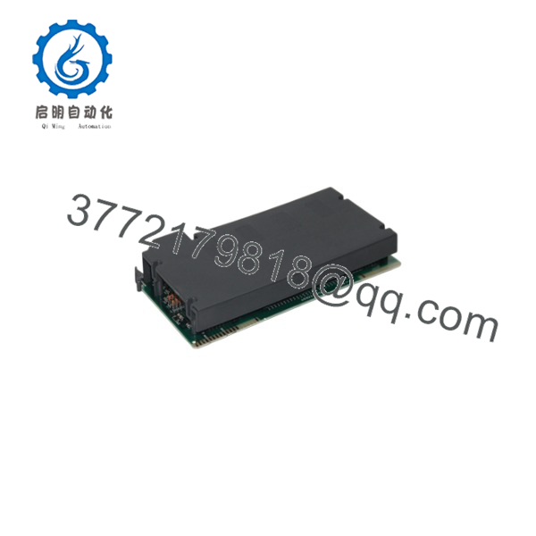
1771-OWNA
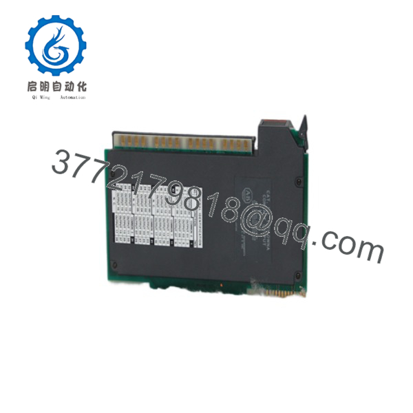
1771-OWNA
5. Installation & Configuration Guide
Stage 1: Pre-Installation Preparation (5–10 min) ⚠️ Safety First: Notify operations of planned downtime. Place the system in a safe state. Lock out/tag out chassis power and field power. Wait at least 5 minutes for capacitor discharge. Tools Required: ESD wrist strap, PH1 or flat screwdriver, multimeter, wire labels, smartphone for photos. Data Backup: Photograph the existing module’s front indicators, terminal wiring, and any adjacent module labels. Note the exact slot number and chassis type. Export any relevant ladder documentation if the processor is still accessible.
Stage 2: Removing the Old Module (5–8 min)
- Confirm power is removed from both the backplane and the field wiring arm.
- Swing the field wiring arm (1771-WN) downward to disconnect it from the module face.
- Release the module locking latch and pull the module straight out of the chassis. Do not rock or twist—backplane pins are easily bent.
- Inspect the backplane connector for bent pins, debris, or corrosion. ⚠️ Keep the old module until the replacement is proven operational.
Stage 3: Installing the New Module (8–12 min)
- Ground yourself with an ESD strap. Verify the new module is marked 1771-OWNA.
- Confirm keying bands are installed between chassis positions 6–8 and 16–18.
- Align the circuit board with the top and bottom card guides. Slide the module fully into the chassis until it seats firmly in the backplane connector.
- Swing the locking latch down over the front edge of the module.
- Re-engage the 1771-WN field wiring arm and tighten terminal screws to 7–9 in-lb. Self-Checklist: [ ] Module fully seated [ ] Latch locked [ ] Wiring arm secured [ ] No bent pins observed.
Stage 4: Power-On & Testing (10–15 min) Pre-Power Check: Use a multimeter to verify no shorts on the 24 V or field power rails.
- Apply chassis backplane power only. Observe the 32 status LEDs—none should be lit until outputs are commanded.
- Apply field power. Force individual outputs in the processor and confirm corresponding LEDs illuminate and the contact closes.
- Verify load current does not exceed 1 A per point or 12 A total at the prevailing ambient temperature.
- Run a short dry-cycle of the process if possible. ⚠️ Troubleshooting Note: If the module draws excessive backplane current or LEDs behave erratically, remove power immediately and re-check seating and keying. Solid red or absent indicators usually indicate a backplane connection or power-supply issue, not a firmware mismatch (this module has no user firmware).
6. Frequently Asked Questions (FAQ)
Q: Can I hot-swap the 1771-OWNA under power? No. Removing or inserting the module or the field wiring arm with backplane or field power applied can arc the connectors and damage the backplane. Always kill power first.
Q: Is the 1771-OWNA still in production? No. The entire PLC-5 / 1771 family is discontinued. Remaining stock is new surplus or refurbished. Plan migration to ControlLogix (1756) when practical.
Q: What is the direct replacement if this module is unavailable? There is no exact drop-in. Common migration paths use 1756-OW16I or 1756-OX8I with conversion wiring arms (e.g., 1492 series). Expect chassis, wiring, and addressing changes.
Q: Will I lose my PLC-5 program when I replace this I/O module? No. The 1771-OWNA is a pure I/O module. Processor memory and logic remain intact provided you do not clear the processor or change the I/O configuration table unnecessarily.
Q: Why is the price lower than historical OEM list price? These are new surplus units from excess inventory. They are genuine Allen-Bradley modules that have never been installed, but they are no longer factory-fresh from Rockwell production lines. Full functional testing and a warranty are provided.
Q: Can I use this module on inductive loads (solenoids, contactors)? Not recommended. The 1771-OWNA has no built-in surge suppression. Inductive kick can weld contacts or shorten life. Use external snubbers or choose a module designed for inductive loads if the application requires it.
Q: What field wiring arm do I need? Use the 1771-WN. Do not mix with the older 1771-WD used on lower-density modules.



