
 WhatsApp: +86 16626708626
 Email:
  Phone: +86 16626708626
Description
3. Key Technical Specifications
| Parameter | Specification Value |
|---|---|
| Catalog Part Number | 1794-OW8 |
| Manufacturer | Allen-Bradley (Rockwell Automation) |
| Compatible Architecture | FLEX I/O Communication Adapters (1794-AENT, 1794-APB, 1794-ASB) |
| Number of Outputs | 8 normally open (Form A) electromechanical relay contacts |
| Output Voltage Range | 5 to 264V AC (47–63 Hz) / 5 to 125V DC |
| Current Rating per Point | 2.0 A continuous maximum |
| Module Current Rating | 16 A total across 8 channels |
| Flexbus Current Draw | 80 mA @ 5V DC |
| Power Dissipation | 5.5 W maximum @ maximum load |
| Off-State Leakage Current | 1.0 mA maximum |
| Isolation Rating | 250V continuous (channel-to-channel and channel-to-Flexbus) |
| Compatible Terminal Base | 1794-TB2, 1794-TB3, 1794-TB3S, 1794-TBN, 1794-TBNF |
4. Product Introduction & Supply Chain Strategy
The Allen-Bradley 1794-OW8 is an 8-point isolated electromechanical relay output module within the versatile FLEX I/O platform. Providing channel-to-channel isolation, it allows mixed-voltage switching (e.g., controlling both 120V AC motor contactors and 24V DC solenoid valves on the same module) without cross-talk or electrical interference.
This product is a Brand New Surplus unit. It is not used, not pulled from a decommissioned plant, and not refurbished. All modules undergo rigorous quality verification to ensure OEM-level reliability.
Securing the 1794-OW8 as New Surplus guarantees continuous operation on distributed plant networks. Refurbished relay cards frequently suffer from pitted or welded contact tips, worn coil springs, or cracked terminal base connectors that trigger intermittent load actuation. Purchasing verified New Surplus provides pristine relay contact surfaces and full electrical isolation integrity while bypassing extended OEM manufacturing lead times.
5. Installation & Configuration Guide
Stage 1: Pre-Installation (Prep & Safety)
- Disconnect main power to the FLEX I/O mounting rail and field power circuits, then apply Lock-Out/Tag-Out (LOTO).
- Attach a grounded ESD wrist strap before handling the module circuit board.
- Verify that the terminal base keyswitch is turned to Position 9 (required setting for the 1794-OW8).
- Inspect the terminal base wiring to confirm proper line fuses or surge suppressors are installed on inductive field loads.
Stage 2: Removal
- Rotate the module latching mechanism on the terminal base to release the card.
- Pull the 1794-OW8 module straight forward off the 1794 terminal base interface pins.
- Ensure the base locking levers remain open.
- Store the removed module in an ESD protective pouch.
Stage 3: Installation (Clone & Seat)
- Confirm the terminal base keyswitch is aligned to Position 9.
- Align the rear circuit board guide tracks of the new 1794-OW8 with the terminal base slot.
- Press the module firmly onto the base until the side latches click securely into place.
- Verify that the module seats flush against adjacent FLEX I/O units.
Stage 4: Power-On & Testing
- Restore main AC/DC supply power to the field circuits and FLEX I/O communication adapter.
- Check the front panel LED indicators: the
POWERLED should illuminate solid green. - Force output bits in your controller environment (Studio 5000, RSLogix 500, or RSLogix 5) and listen for mechanical relay clicks while checking channel status LEDs.
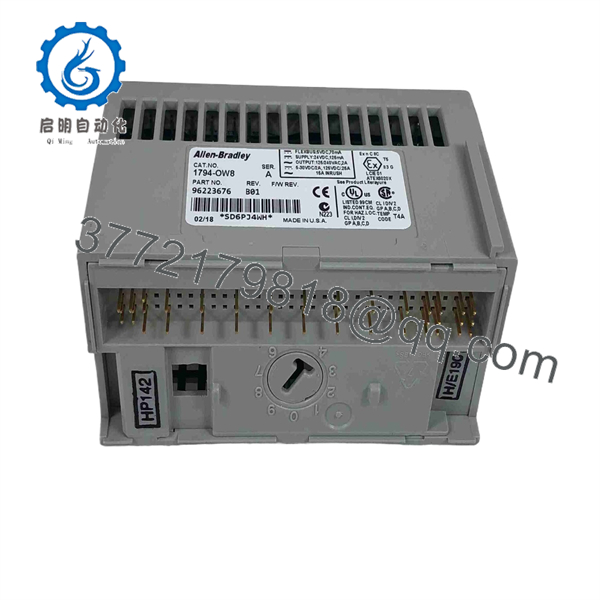
1794-OW8
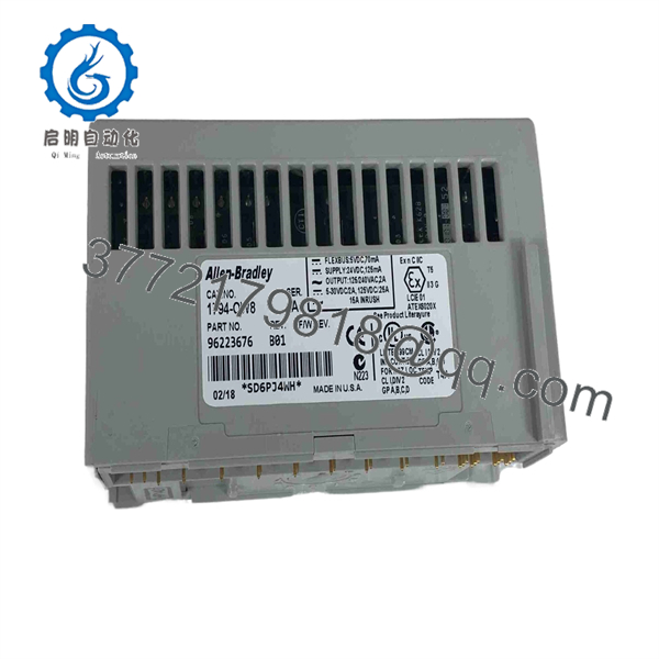
1794-OW8
6. Firmware/Software Versions & Upgrade Notes
The 1794-OW8 functions as a hardware-transparent discrete output block across multiple remote I/O networks.
- Network Adapter Compatibility: Interfaces seamlessly with EtherNet/IP (1794-AENT/AENTR), PROFIBUS (1794-APB), and Remote I/O (1794-ASB) adapters.
- Contact Arc Suppression: When switching inductive loads (such as heavy relay coils or motor starters), install external RC networks across AC loads or flyback diodes across DC loads to extend relay contact life.
- Fused Base Alternative: For installations requiring individual channel fuse protection directly on the mounting base, pair the 1794-OW8 with a 1794-TBNF terminal base unit.
7. Frequently Asked Questions (FAQ)
Q: Is this 1794-OW8 module brand new or has it been pulled from a decommissioned panel?
A: This product is a Brand New Surplus unit. It is not used, not pulled from a decommissioned plant, and not refurbished. All modules undergo rigorous quality verification to ensure OEM-level reliability.
Q: What terminal base keyswitch position is required for the 1794-OW8?
A: Set the terminal base keyswitch dial to Position 9 prior to inserting the 1794-OW8 module.
Q: Can I mix AC and DC voltages on different channels of the same 1794-OW8 module?
A: Yes. Because all 8 channels feature full optical and channel-to-channel relay isolation (rated up to 250V continuous), you can safely mix different AC and DC control voltages across the module terminals.
Q: What is the maximum continuous current rating per relay contact?
A: Each relay contact is rated for up to 2.0 A continuous, with a total module capacity limit of 16 A across all 8 points simultaneously.
Q: What warranty applies to this New Surplus module?
A: We back this card with a full 1-year functional replacement warranty from the date of shipment, ensuring complete operational protection for your distributed I/O architecture.



