
 WhatsApp: +86 16626708626
 Email:
  Phone: +86 16626708626
Description
Key Technical Specifications
| Parameter | Value |
|---|---|
| Manufacturer | Allen-Bradley / Rockwell Automation |
| Part Number | 354792-A01 |
| Related Catalog Number | 20B-ENC-1 |
| Related Assembly Number | 319284-A01 |
| Product Family | PowerFlex 700 |
| Product Type | Encoder Interface Board / Encoder Interface Kit |
| Encoder Type | Incremental, dual channel |
| Encoder Supply | 5 V or 12 V, jumper selectable |
| Internal 12 V Supply | 250 mA |
| Maximum Input Frequency | 250 kHz |
| Encoder Inputs | A, A/, B, B/, Z, Z/ |
| Control Application | PowerFlex 700 vector control |
| Encoder Output Requirement | Line-driver type, single-ended or differential |
| Mounting/Application | PowerFlex 700 drive feedback interface |
Rockwell’s PowerFlex 700 documentation specifies encoder terminals for A, A/, B, B/, Z, and Z/ signals. The 20B-ENC-1 supports jumper-selectable 5 V/12 V operation.
For the documented encoder interface, the input specification is an incremental dual-channel encoder with 12 V supply, 250 mA available drive power, and a maximum input frequency of 250 kHz. The encoder must provide an appropriate line-driver output and meet the voltage/current requirements in the PowerFlex 700 documentation.
Identification caution: Current third-party listings associate 354792-A01 with the 20B-ENC-1 / 319284-A01 encoder interface assembly, but the exact physical revision should be checked against the board label before procurement.
Product Introduction
The Allen-Bradley 354792-A01 is an encoder interface PCB associated with the PowerFlex 700 adjustable-frequency drive platform. It provides the drive with incremental encoder feedback through A/B channels and the optional Z marker channel. The associated 20B-ENC-1 interface supports jumper-selectable 5 V/12 V encoder operation.
This board is primarily relevant to PowerFlex 700 applications requiring closed-loop vector control and encoder feedback. When replacing one, verify the board revision, encoder voltage selection, wiring polarity, and drive configuration rather than treating it as a generic feedback card.
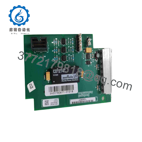
354792-A01
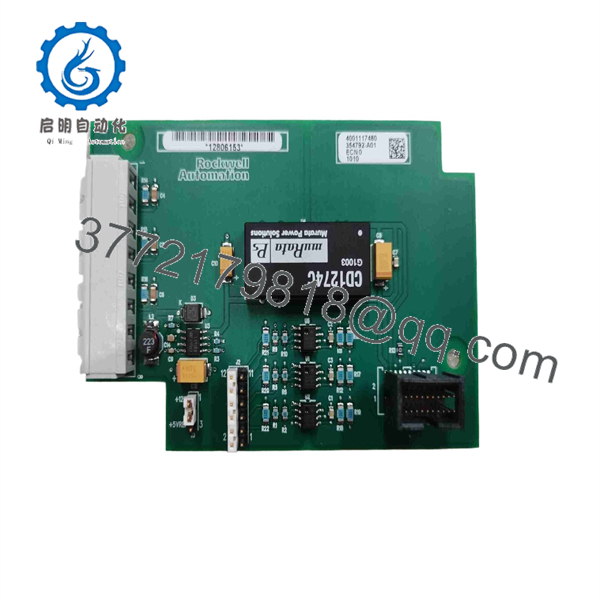
354792-A01
Installation & Configuration Guide
Stage 1: Pre-Installation Preparation — Approx. 10 Minutes
⚠️ Safety First
- Notify operations and obtain an approved maintenance window.
- Stop the associated motor and place the machine in a safe state.
- Apply lockout/tagout (LOTO) to the PowerFlex 700.
- Verify that the drive is de-energized with a properly rated meter.
- Follow the PowerFlex 700 discharge-time requirements before accessing internal components.
- Do not rely solely on the HIM display to establish zero voltage.
Tools Required
- ESD wrist strap
- PH1/appropriate Phillips screwdriver
- Calibrated multimeter
- Wire labels
- Smartphone or camera
- Torque-controlled screwdriver where specified
- PowerFlex 700 documentation
Data Backup
Before removing the board:
- Record the complete drive catalog number and series.
- Record the installed firmware revision.
- Save or document the existing drive parameter configuration.
- Photograph the encoder wiring.
- Photograph the 5 V/12 V jumper configuration.
- Record encoder manufacturer, model, supply voltage, and pulses/revolution.
- Photograph the existing 354792-A01 board from multiple angles.
⚠️ The jumper setting deserves special attention. The PowerFlex 700 documentation specifically identifies selectable 5 V/12 V encoder operation on the 20B-ENC-1 board.
Stage 2: Removing the Old Encoder Board — Approx. 5 Minutes
- Confirm the DC bus is at a safe voltage before opening the drive.
- Remove the required PowerFlex 700 covers.
- Label each encoder conductor.
- Photograph the terminal arrangement before disconnecting anything.
- Disconnect the encoder wiring carefully.
- Record the shield termination arrangement.
- Remove the retaining hardware securing the encoder interface board.
- Pull the board straight out without twisting the connector.
- Inspect the mating connector for bent contacts, contamination, or heat damage.
⚠️ Do not wire the replacement from memory. PowerFlex 700 encoder terminals have dedicated functions. Terminals include +12 V, common, Z/Z/, B/B/, and A/A/.
Stage 3: Installing 354792-A01 — Approx. 5–10 Minutes
- Verify the replacement board marking and revision.
- Confirm compatibility with the installed PowerFlex 700 drive.
- Compare the new board against the original before installation.
- Clone the original jumper configuration.
- Confirm whether the encoder requires 5 V or 12 V operation.
- Install the board without forcing the connector.
- Secure the board using the appropriate hardware.
- Reconnect A, A/, B, B/, Z, Z/, supply, and common conductors according to the applicable wiring diagram.
- Re-establish the shield connection according to the PowerFlex 700 installation documentation.
- Verify that no conductor can contact adjacent terminals or chassis metalwork.
The PowerFlex 700 documentation identifies A as the single-channel or quadrature A input, B as the quadrature B input, and Z as the pulse/marker input.
Self-Checklist
- Correct 354792-A01 board installed
- Board revision documented
- 5 V/12 V jumper verified
- A/A/ wiring verified
- B/B/ wiring verified
- Z/Z/ wiring verified if used
- Encoder shield connection verified
- Board connector fully seated
- Drive covers correctly reinstalled
Stage 4: Power-On & Testing — Approx. 10–15 Minutes
- Perform a final wiring inspection before energizing.
- Verify that no tools or loose conductors remain inside the drive.
- Restore power according to the plant procedure.
- Check the PowerFlex 700 for initialization or fault indications.
- Confirm the drive’s encoder/feedback configuration.
- Verify the encoder supply voltage matches the selected board jumper.
- Run the motor at low speed under controlled conditions.
- Check actual speed feedback against the expected encoder feedback.
- Test forward and reverse operation if permitted by the commissioning procedure.
- Check for encoder loss, feedback instability, overspeed, or direction faults.
- Record the final parameter settings and board identification.
⚠️ If the drive reports incorrect speed, unstable feedback, or an encoder fault, stop the test. Check the encoder supply selection, A/B polarity, shielding, grounding, and encoder specification before changing drive parameters.
Frequently Asked Questions (FAQ)
Q1. What is Allen-Bradley 354792-A01?
354792-A01 is an encoder interface PCB associated with the PowerFlex 700 drive platform. Current cross-reference listings identify it with the 20B-ENC-1 PowerFlex 700 Encoder Interface Kit and 319284-A01 assembly.
Q2. Is 354792-A01 the same as 20B-?
The available documentation and distributor cross-references associate 354792-A01 with 20B-, but they are not necessarily interchangeable part-number conventions in every purchasing or service context. Rockwell’s current catalog identifies as the PowerFlex 700 Encoder Interface Kit. Verify the exact marking on the existing board before ordering.
Q3. What encoder voltage does this board support?
The associated 20B- supports 5 V/12 V encoder operation, with the selection made through the board’s jumper configuration. Do not assume the correct setting from the motor nameplate. Check the encoder manufacturer’s specification and photograph the old board before replacement.
Q4. What type of encoder can the PowerFlex 700 interface accept?
The documented interface is intended for incremental, dual-channel encoder feedback. The PowerFlex 700 documentation specifies A/B quadrature signals and a Z marker/pulse channel. The encoder can use single-ended or differential signaling when it meets the specified electrical requirements.
Q5. Can I hot-swap 354792-A01?
No. Treat it as a de-energized drive maintenance procedure. The encoder interface is installed inside the PowerFlex 700 drive, so remove power and verify the DC bus is discharged before accessing the board. Follow the applicable PowerFlex 700 installation instructions and plant LOTO procedure.
Q6. Is this part obsolete?
The associated 20B- is currently listed by Rockwell Automation as End of Life. Rockwell states a discontinuation date of June 30, 2028 and currently lists no planned Rockwell replacement.
That makes exact-part verification important for legacy PowerFlex 700 installations. Do not substitute another encoder interface simply because the connector appears similar.
Q7. What condition should I specify when purchasing 354792-A01?
Specify the condition explicitly: Factory Sealed, New Original/New Surplus, or Refurbished (tested). Ask for photographs of the actual board label, revision marking, connectors, and packaging. Current market listings show multiple conditions, including new/surplus and refurbished units, so “new” should not be accepted without clarification.



