
 WhatsApp: +86 16626708626
 Email:
  Phone: +86 16626708626
Description
3. Key Technical Specifications
- Module Type: Analog interface / signal conditioning PCB
- System Platform: Alstom / Converteam ALSPA control architecture
- Function: Analog signal acquisition and distribution within DCS rack
- Input Type: Industrial analog signals (voltage/current loop depending on configuration)
- Output Type: Processed analog signals to controller/I/O backplane
- Backplane Interface: Proprietary edge connector (rack-mounted system bus)
- Power Supply: Supplied via system backplane (typically 5–24 V DC internal rails)
- Channel Density: Multi-channel analog interface (exact count system-dependent by revision)
- Signal Isolation: Galvanic isolation typical for plant-grade signal conditioning modules
- Operating Environment: Power generation, turbine control, heavy industrial automation
- Cooling: Passive convection inside sealed cabinet
- EMC Design: High immunity to industrial noise environments
- Failure Modes: Connector oxidation, aging op-amps, capacitor degradation, thermal drift
- Revision Sensitivity: High (firmware + hardware pairing with rack generation required)
4. Product Introduction
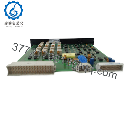
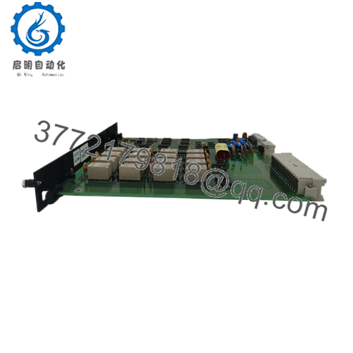
The ALSTOM 029.221719/01 is an analog interface PCB module used in legacy Alstom ALSPA and Converteam distributed control systems. It is typically deployed in turbine control racks and industrial process automation systems where analog field signals must be conditioned and routed into the central control architecture.
Its role is strictly system-internal signal handling. It processes and conditions analog inputs and outputs within a proprietary rack backplane environment and is not designed for standalone operation or modern PLC interoperability without full system integration engineering.

- 029.221719/01
5. Installation & Configuration Guide
Stage 1: Pre-Installation Preparation (10–15 min)
- ⚠️ Confirm full plant shutdown (turbine/process interlock mandatory in critical environments)
- Apply Lockout/Tagout (LOTO) on all rack power feeds
- Verify zero voltage on backplane using calibrated multimeter
- Required tools:
- ESD wrist strap
- Precision screwdriver set
- Multimeter
- Labeling kit
- Camera for wiring documentation
- Record before removal:
- Slot position in rack
- Signal cable assignments (analog inputs/outputs)
- Adjacent module types
- Connector orientation and keying
Stage 2: Removing the Old Module (10–20 min)
- Open control cabinet and locate ALSPA rack
- Label adjacent modules to preserve signal mapping
- Disconnect any external analog field wiring if present
- Release PCB ejector locking mechanism
- Pull module straight out—avoid flexing backplane connector
- Store removed module in ESD-safe packaging
⚠️ Do not rock the board side-to-side. Backplane pin deformation is a common irreversible failure mode in ALSPA racks.
Stage 3: Installing the New Module (10–20 min)
- Verify exact part number: 029.221719/01 (revision must match system generation)
- Inspect rack slot for dust, corrosion, or bent pins
- Align PCB carefully with guide rails
- Insert evenly until full backplane engagement is confirmed
- Lock ejector tabs fully
- Reconnect analog field wiring following documentation
Self-check:
- Full seating confirmed
- No connector tilt or resistance
- Lock mechanism engaged
- Wiring matches pre-removal documentation
Stage 4: Power-On & Testing (10–15 min)
- Energize rack power only (field loops isolated initially)
- Observe system diagnostics / module recognition
- Verify analog signal presence using calibration tools or DCS diagnostics
- Check stability of input/output scaling
- Gradually reintroduce process signals
⚠️ If signals drift or saturate immediately:
- Check calibration mismatch
- Verify revision compatibility
- Inspect grounding and shielding integrity
6. Frequently Asked Questions (FAQ)
1. What is the ALSTOM 029.221719/01 used for?
It is an analog interface module used inside ALSPA/Converteam DCS systems to condition and route analog process signals within turbine or industrial control racks.
2. Is this module still manufactured?
No. It is a discontinued legacy component. Availability is limited to surplus, recovered, or refurbished industrial stock.
3. Can it be used outside ALSTOM systems?
No. It requires a proprietary ALSPA backplane architecture and is not compatible with standard PLC analog I/O modules.
4. What typically fails in this module?
Most issues come from aging analog components (op-amps, capacitors), connector oxidation, and long-term thermal drift.
5. Can I hot-swap this module?
No. Removing it under power can interrupt analog control loops and destabilize plant control systems.
6. Are all 029.221719/01 modules identical?
No. Revision level and calibration configuration vary; compatibility must be confirmed against rack documentation.
7. Why is this module still used in plants?
Many installed turbine and power control systems remain operational for decades, making legacy spare availability critical for maintenance continuity.



