
 WhatsApp: +86 16626708626
 Email:
  Phone: +86 16626708626
Description
Key Technical Specifications
| Parameter | Value |
| Manufacturer | Alstom (Alspa Control Systems) |
| Model Number | AS111 / AS111-2 (OEM Code: C0200550) |
| Module Type | Analog Output Module |
| Number of Channels | 8 Independent Output Channels |
| Signal Ranges | 0 to 20 mA or 4 to 20 mA current loops |
| Process Base Voltage | 24 V DC nominal (19.2 to 30 V DC operating window) |
| Digital Isolation | Integrated optoelectronic isolation from processing core |
| Resolution | 16-bit digital-to-analog converter precision |
| Response Time | Less than 1 ms loop update execution |
| Overcurrent Protection | CTP protection (0.75 A main line, 0.3 A individual channel) |
| Terminal Compatibility | Mounts cleanly onto UT129, UT150, or UT156 baseboards |
| Operating Temp | 0 to +60 °C local cabinet limits |
Product Introduction & Supply Chain Strategy
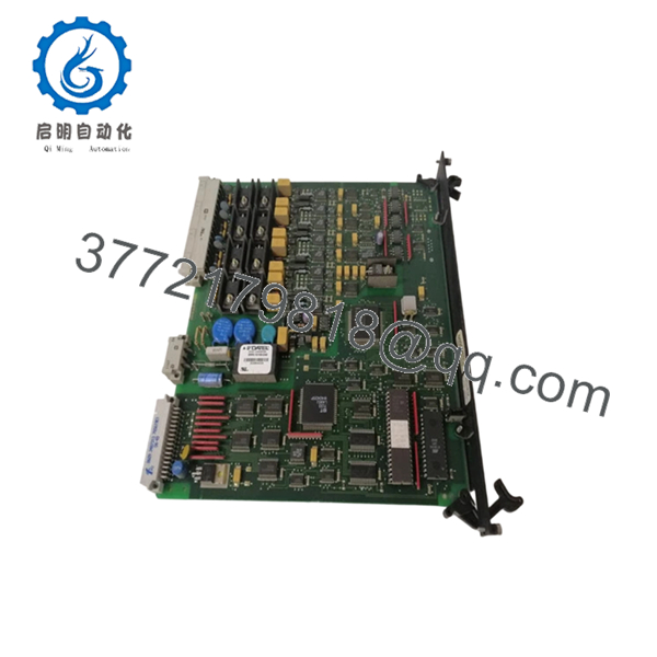
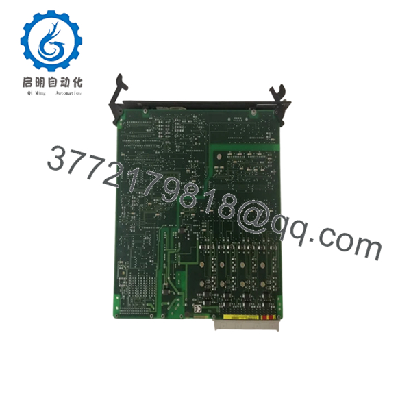
The Alstom AS111 is a high-reliability analog output module engineered for the Alspa CE2000 and CE3000 Distributed Control Systems (DCS). Functioning as a primary field interface card, this module translates 16-bit digital commands from the host controller into continuous 4-20 mA or 0-20 mA current signals to drive servo amplifiers, control valves, and governor positioners. Its robust architecture features electrical isolation between the digital logic backplane and field loops, alongside built-in CTP thermistor safety limits on each channel to isolate loop shorts.
Because this hardware has reached obsolete status, keeping a new surplus module on-site serves as a critical asset insurance policy against long-term operational loss. Procuring this part as a genuine New Surplus unit provides a lower Total Cost of Ownership (TCO) compared to the downstream expenses of unpredicted outages. Choosing a fully verified surplus card removes the severe hazards of component fatigue or degraded capacitors often found in standard refurbished hardware, ensuring your legacy power plant or industrial line maintains full lifecycle reliability.

- AS111
- AS111
Installation & Configuration Guide
Stage 1: Pre-Installation (Prep & Safety)
- Initiate site lock-out/tag-out (LOTO) protocols to isolate all mains and auxiliary power feeding the destination DCS rack.
- Confirm with a digital multimeter that the 24 V DC process line is completely dead before removing any panel covers.
- Secure a grounded ESD wrist strap to your arm and clamp it to an unpainted grounded structural rail.
- Document the module details. Take clear photos of any hardware configuration settings, daughtercard revisions, and terminal connection paths to ensure accurate field replication.
Stage 2: Removal
- Loosen the front faceplate captive mounting hardware on the existing AS111 board.
- Carefully pull any front-facing terminal connectors or wiring blocks away from the card frame using a uniform backing tool.
- Pull the module straight forward out of its rack position along the chassis tracking slots. Keep the board perfectly perpendicular to prevent bending the rear backplane connectors.
- Immediately secure the older assembly inside an antistatic ESD shielding container.
Stage 3: Installation (Clone & Seat)
- Extract the new surplus AS111 card from its factory-sealed ESD packaging inside a static-safe zone.
- Verify that the incoming board color and revision match your baseboard type (such as UT129 or UT150 configurations).
- Slide the board smoothly down the chassis tracking lanes until the rear bus pins lock fully into the matching backplane socket.
- Hand-tighten all integrated faceplate anchoring screws to establish continuous ground path continuity, and snap the terminal connection blocks back onto the board face.
Stage 4: Power-On & Testing
- Test the incoming 24 V DC line to ensure the voltage level reads between 19.2 and 30 V DC.
- Re-energize the master circuit breaker to power up the DCS rack.
- Observe the front indicator assembly: verify that the system initialization sequence concludes with a stable, green operational status light and zero red error indications.
- Access your Alspa engineering terminal to run a standard loopback test, verifying sub-millisecond response rates and checking that output milliamps scale exactly to your software configuration commands.
Firmware/Software Versions & Upgrade Notes
The Alstom AS111 module depends on precise firmware matching to maintain synchronization with your Alspa system controllers. Standard factory builds are often configured with Firmware Revision A.05.00 (or similar based on your hardware revision suffix), which ensures proper communication across legacy processing platforms.
When managing a hardware swap, do not modify firmware parameters on an active rack or drop a different revision card into a redundant pair architecture. Doing so can trigger instant bus synchronization timeouts or cause the host processor to flag a mismatch fault. Always match the firmware revision printed on the incoming module’s label with your existing system topology before executing full loop calibration.
Frequently Asked Questions (FAQ)
Q: What is the exact physical difference between the AS111-1 and AS111-2 variations? A: The primary difference lies in the process voltage optimizations and electrical protection tuning. The AS111-2 is specifically designed and certified for standard 24 V DC industrial process networks, incorporating precise CTP overcurrent safety thresholds (0.75 A main, 0.3 A per channel) to safely isolate localized loop errors without dropping out adjacent field channels.
Q: Are these cards truly new surplus, or have they been extracted from decommissioned systems? A: These modules are 100% genuine New Surplus stock. They have never been placed into active industrial service, nor were they pulled from running systems. Each unit remains in factory-clean condition with unmarred backplane connector contacts and original circuit board traces, opened only for our standard inbound quality assurance verification.
Q: Can this analog card handle both 0-20 mA and 4-20 mA instruments on the same module? A: Yes. The module provides 8 independent channels that can be scaled and mapped via your Alspa system programming environment to handle both 0-20 mA and standard 4-20 mA live loops, depending on your target field valve or actuator specifications.
Q: Why choose New Surplus over a much cheaper refurbished or remanufactured AS111 board? A: Industrial analog modules face severe aging from heat and continuous current loops. Refurbished boards are used parts that have already logged thousands of hours, leaving their internal capacitors vulnerable to latent fatigue. Sourcing a New Surplus card gives you an untouched component with its full factory design life intact, eliminating the high cost of unexpected downtime caused by cheap, second-hand components.
Q: How do I know if this AS111 board will physically mount onto my existing Alspa baseboard? A: The AS111 series features a highly standardized footprint that maintains direct form-factor compatibility with popular Alspa termination panels, including the UT129, UT150, and UT156 models. Both black and blue card profiles are fully interchangeable across these standard base plates.



