
 WhatsApp: +86 16626708626
 Email:
  Phone: +86 16626708626
Description
Key Technical Specifications
| Parameter | Value |
|---|---|
| Manufacturer | Alstom / Converteam |
| Model Number | DAP232 |
| Part Number | 590.043150 |
| Alternate Formatting | 590043150 / 590.043.150 |
| Product Type | Unit Processor LP 32-digital output module |
| Output Type | Discrete DC outputs |
| Output Channel Count | 32 |
| Nominal Output Voltage | 24 V DC |
| Listed Current Rating | 0.5 A; confirm whether this is per channel, module input, or another listing-specific rating before installation |
| Primary Function | Converts controller commands into discrete field-control outputs |
| Typical Loads | Interposing relays, contactors through relay interfaces, solenoids, lamps, annunciators, and digital field interfaces |
| Installation | Dedicated Alstom/Converteam automation rack or compatible unit-processor assembly |
| Lifecycle Status | Discontinued by manufacturer according to reseller listings |
| Replacement Requirement | Match DAP232 type, 590.043150 part number, revision, rack position, field wiring, and output type |
Multiple listings identify DAP232 part number 590.043150 as an Alstom/Converteam unit-processor card with 32 digital outputs at 24 V DC. One listing reports a 0.5 A rating, but it does not clearly establish whether that figure applies per output, per output group, or to the full module; verify the OEM manual before sizing loads or fuses.
Product Introduction
Alstom DAP232 590.043150 is a Unit Processor LP digital-output card for legacy Alstom or Converteam industrial automation hardware. The module provides 32 discrete 24 V DC output points for switching field-interface devices such as relay coils, solenoid interfaces, lamps, annunciators, and other low-power DC control loads.
The key procurement requirement is exact identity. Match both DAP232 and 590.043150, then verify the output architecture, installed rack, terminal arrangement, output commoning, and protection scheme. Do not substitute an input, relay-output, or different transistor-output card based only on a similar housing.
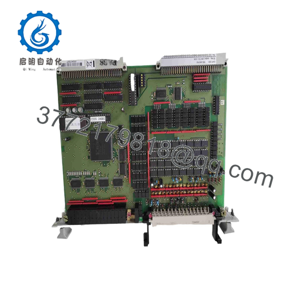
DAP232 590.043150
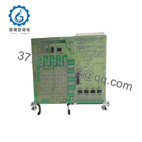
DAP232 590.043150
Troubleshooting Quick Reference
| Symptom | Possible Cause | Relevance to This Part | Quick Check Method | Recommendation |
|---|---|---|---|---|
| No outputs operate on any channel | Missing 24 V DC field supply, blown group fuse, failed rack supply, controller fault, loose module seating, or failed DAP232 | ✅ High | Measure 24 V DC at the module’s field-supply terminals using the wiring diagram. Then measure the rack/control supply and inspect module seating. | Check the external 24 V DC source, fuses, and common return before replacing the card. |
| One output will not energize | Open field wire, failed relay coil, failed solenoid, blown channel protection, wrong controller logic, or failed output transistor | ✅ High | Force the command only under an approved maintenance procedure. Measure voltage at the output terminal and at the load. Compare with a working channel. | If the command is active and voltage is absent at the verified output terminal, investigate that channel or module. |
| Output LED is on but field device stays off | Open circuit, bad load, faulty relay interface, incorrect return connection, failed load fuse, or insufficient field voltage | ❌ Low | Measure 24 V DC directly across the load terminals while the output is commanded on. Check coil resistance with power isolated. | Do not replace just because its LED is on. The card may be doing its job while the external circuit is open. |
| Field device stays energized after command goes off | Welded relay contacts, external backfeed, wiring short, wrong logic, failed output transistor, or incorrect output-common wiring | ✅ Medium | Remove the controller command if safe, then measure output voltage and trace any voltage present from external sources. Inspect interposing relays for welded contacts. | Identify backfeed and relay faults first. If voltage remains at the card output with command removed and wiring isolated, the channel may be damaged. |
| Several adjacent outputs fail together | Blown output-group fuse, missing group common, shared 24 V DC supply fault, connector problem, or damaged output group | ✅ High | Use the wiring drawing to identify the output group. Measure the group supply and common at the terminal block; compare with a working group. | A grouped failure usually points to shared field power or common wiring, not 32 individual output failures. |
| Controller indicates output active but no terminal voltage | Configuration mismatch, output inhibited, interlock active, module communication issue, faulty channel, or wrong module type installed | ✅ Medium | Verify the logic state online, then check module diagnostic LEDs and measure at the corresponding physical terminal. Confirm the configured I/O type matches . | Confirm configuration and interlocks before replacing hardware. |
| Output voltage collapses when load is connected | Overcurrent, shorted field cable, failing coil, incorrect load type, insufficient external power supply, or damaged output stage | ✅ High | Disconnect the field load under approved isolation. Test the channel into a suitably rated load or compare output behavior with no load and normal load. | Find and correct the downstream overload before installing another . |
| Module heats up, smells burnt, or shows discoloration | Shorted load, overload, loose terminal, incorrect polarity, internal failure, or poor cabinet ventilation | ✅ High | Isolate power immediately. Inspect output wiring, field loads, terminal torque, and module housing. Use thermal imaging only after safe re-energization. | Do not reapply power repeatedly. Replace the card only after the external short or overload has been removed. |
❗ Do not assume the 0.5 A listing applies per channel. That number appears in secondary-market data without a clear rating basis. Until the OEM manual confirms it, use interposing relays or properly rated interface modules for inductive loads rather than driving large solenoids or contactors directly.
❗ Take a terminal photo before removal. On a 32-point card, one shifted wire can create a fault that looks like a bad module. Photograph every terminal strip, output tag, common, fuse, and shield connection before touching the old unit.
❗ Suppress inductive loads correctly. A bare relay coil or solenoid can send a voltage transient back into the output circuit. Use the suppression method specified by the machine design—typically a DC flyback diode, TVS device, or approved relay interface. Do not improvise on circuits tied to safety or high-speed sequencing functions.
If the fault remains unclear, provide technical support with module-label photos, the rack position, output-channel tag, controller logic state, terminal voltage readings, field-device resistance, and photographs of the relevant fuse or relay interface.
Frequently Asked Questions (FAQ)
What is Alstom 590.043150?
590.043150 is a legacy Alstom/Converteam Unit Processor LP card identified as a 32-point digital-output module with 24 V DC outputs. It receives discrete output commands from the automation system and switches compatible field loads through its 32 output channels.
Is 590.043150 a PLC CPU?
No. Although some sellers use broad terms such as “processor board” or “controller module,” the available part descriptions identify it as a Unit Processor LP 32-digital-output card. Treat it as an output module unless the unit label and OEM documentation for your exact rack show otherwise.
Does the module provide 32 outputs at 24 V DC?
That is the consistent description across several product listings: 32 digital outputs with 24 V DC output capability. However, verify whether the outputs are sourcing or sinking, their common arrangement, channel grouping, permissible load type, and current limits before connecting a replacement. Those details determine whether the module can drive your existing field circuit safely.
What does the 0.5 A rating mean?
One reseller listing states “0.5 amp” for 590.043150 but does not define whether that means per point, per group, or a module-level specification. Do not size a load from that number alone. Check the original Alstom/Converteam technical documentation or measure the installed circuit and use approved interposing relays for anything beyond clearly documented output capability.
Can I hot-swap the module?
Assume no unless the exact rack documentation explicitly permits hot replacement. Pulling a live 24 V DC output card can interrupt relays, trip sequencing, drop contactors, create transient voltages, damage the backplane, or cause uncontrolled process behavior.
First put the machine or process in a safe condition. Disable commands, isolate field power where required, follow lockout/tagout rules, discharge stored energy, then use ESD protection while replacing the card.
Why is one output bad while all other channels work?
Single-channel failure usually points to one of five places: the output transistor, field wiring, terminal connection, fuse or group protection, the interposing relay, or the field load itself. Start at the actual output terminal. If the controller command is active but the terminal does not switch on a known-good test circuit, the channel may be defective.
It is the classic maintenance trap: technicians change the card first, then find a broken wire at the solenoid. Check the field circuit before you spend money on a hard-to-find spare.
Is 590.043150 obsolete?
Yes, treat it as a discontinued legacy part. A reseller listing explicitly marks 590.043150 as discontinued by the manufacturer. Availability will depend on surplus inventory, professionally tested used stock, and the seller’s ability to identify the exact revision. Keep one verified spare if this card is critical to production.
Is New Surplus better than Refurbished for this module?
It depends on the evidence, not the label alone.
- New Original / New Surplus: Unused stock from warehouse inventory, project surplus, or liquidation. Request photos of the original label, packaging, terminals, connectors, seals, and date codes.
- Refurbished (tested): Previously used material that has been inspected and functionally tested. Request channel-by-channel output test results.
- Used, untested: Lowest confidence. Use only if you can bench-test it before a shutdown or accept the risk.
For an outage-critical output card, a tested unit with documented 32-channel verification is generally safer than unverified “new old stock.”
What testing should I request from the supplier?
Request a test record for the actual card being shipped:
- Verification of and 590.043150 labels, revisions, serial numbers, and connector layout
- Visual inspection for corrosion, cracked housings, damaged terminals, overheated areas, rework marks, and bent connector contacts
- ESD-safe handling and packaging
- Power-up test in a compatible Alstom or Converteam rack, where available
- Command-and-measure testing of all 32 output points
- Output-voltage verification at low, mid, and expected operating load conditions
- Controlled load test using a properly rated resistive load or relay-interface test fixture
- Check for abnormal thermal rise during sustained operation
- Dated test report, QC sign-off, and photos or video on request
For a 32-point DC output module, “powers on” is not enough. Ask whether every channel was commanded and measured.



