
 WhatsApp: +86 16626708626
 Email:
  Phone: +86 16626708626
Description
Key Technical Specifications
Publicly available documentation for the EP3-E-4-A is inconsistent on several hardware details, so the following specifications should be treated as configuration-dependent until confirmed against the unit nameplate and OEM documentation. The strongest recurring identification is the EPIC III / ESP controller application.
- Model: EP3-E-4-A
- Manufacturer: Alstom
- Series: EPIC III
- Application: Electrostatic precipitator control
- Controller Type: Automatic Voltage Controller (AVC)
- Power Supply: 110/220 VAC, 50/60 Hz — reported specification
- Analog Inputs: 4 isolated analog acquisition channels — reported specification
- Analog Signal Range: 0–10 V / 4–20 mA — reported specification
- Control Output: SCR/thyristor phase-shift firing control
- Communication: Ethernet and RS-485 / Modbus RTU reported on available technical listings
- Operating Temperature: −10 °C to +60 °C — reported configuration range
- Enclosure/Application: Cabinet-mounted industrial control equipment
- Typical Function: Transformer-rectifier voltage/current regulation, spark detection and recovery
- Typical Industries: Power generation, cement, steel, waste incineration and other ESP applications
The available technical sources describe the EP3-E-4-A as an ESP controller responsible for regulating transformer-rectifier operation and responding to spark or flashover conditions. One source specifically identifies four isolated analog acquisition channels for primary current, secondary voltage, secondary current and opacity feedback.
Technical verification note: Do not order this module solely from a generic EPIC III description. Public listings give conflicting dimensions, weight, processor/I/O counts and communication details. Match the complete part number, hardware revision, terminal arrangement, cabinet configuration and existing controller documentation before replacement.
Product Introduction
The Alstom EP3-E-4-A is an EPIC III automatic voltage controller used in electrostatic precipitator (ESP) systems. Its primary role is to control transformer-rectifier operation, process electrical feedback from the ESP field, and respond to spark or flashover conditions. Available documentation identifies the unit as an AVC for high-voltage ESP applications.
For maintenance teams supporting legacy Alstom ESP installations, the EP3-E-4-A is primarily a replacement and continuity-of-operation component. Its exact I/O, communications and electrical configuration should be confirmed against the installed unit before procurement because published specifications vary between sources.
EP3-E-4-A
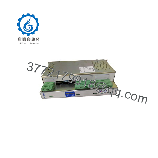
EP3-E-4-A
Installation & Configuration Guide
Estimated replacement time: 20–30 minutes for a prepared cabinet and a technician familiar with the EPIC III installation. Actual commissioning time can be substantially longer if firmware, parameter files or ESP calibration data must be reconstructed.
Stage 1: Pre-Installation Preparation — 5–10 minutes
- ⚠️ Place the ESP system in a safe operating state. Coordinate the shutdown with operations and follow the site’s electrical safety procedure.
- Apply lockout/tagout to the applicable control and high-voltage equipment. An ESP transformer-rectifier system is not an ordinary PLC cabinet; verify that stored electrical energy and high-voltage isolation requirements have been addressed.
- Allow the equipment to discharge according to the site’s approved procedure. Do not rely on a generic five-minute waiting period when the equipment manufacturer’s procedure specifies a longer interval.
- Prepare:
- ESD wrist strap
- Insulated screwdriver set
- Digital multimeter
- Wire labels
- Smartphone or camera
- Existing EPIC III drawings and parameter records
- Record the existing configuration. Photograph terminal wiring, address/configuration switches, connectors and every front-panel setting before removing the old EP3-E-4-A.
- Record the existing controller’s firmware/hardware revision and parameter values, if accessible.
- Save any available ESP controller configuration or commissioning data before disturbing the system.
Stage 2: Removing the Old Module — 5 minutes
- Verify that the replacement label reads and compare the complete identification information with the installed unit.
- Photograph the module one more time before disconnection.
- Label every field connection that could be confused during reinstallation.
- Disconnect wiring without pulling on individual conductors.
- Release the applicable rack, panel or mounting hardware.
- Remove the module straight and carefully. Avoid stressing connectors or backplane contacts.
- Inspect the mating connector, terminals and surrounding cabinet for:
- Bent contacts
- Corrosion
- Loose terminals
- Dust contamination
- Heat discoloration
- ⚠️ Keep the removed controller available until commissioning is complete. It remains the best reference for configuration and wiring if something does not match the replacement.
Stage 3: Installing the New Module — 5–10 minutes
- Use ESD protection before handling the replacement electronics.
- Verify the complete part number and hardware identification against the removed controller.
- Clone the original configuration. Reproduce documented switches, jumpers and adjustable parameters exactly where applicable.
- Reconnect wiring according to the original photographs and approved electrical drawings.
- Check polarity and signal identification on every analog feedback circuit.
- Secure the module using the original mounting hardware.
- Check that all connectors and terminal blocks are fully seated.
- Perform a visual inspection before applying power.
Self-check:
- Exact model confirmed
- Hardware/revision information recorded
- Configuration copied
- Analog feedback wiring verified
- Control wiring verified
- Connectors fully seated
- Mounting hardware secured
- ESD precautions completed
Stage 4: Power-On & Testing — 10+ minutes
- Do not immediately energize the ESP high-voltage section. Commission the controller and low-voltage control circuits first.
- Check the applicable supply voltage with a multimeter before connecting the controller.
- Energize the control cabinet according to the approved commissioning sequence.
- Observe front-panel status indicators and verify that the controller completes its normal startup sequence.
- Check communication with the associated supervisory or control system if the installation uses a serial or Ethernet interface.
- Verify configured feedback values for:
- Primary current
- Secondary voltage
- Secondary current
- Other configured process feedback
- Confirm that the controller does not report a persistent fault or communication alarm.
- Perform a controlled functional test before returning the ESP field to normal service.
- Verify transformer-rectifier control response and spark/flashover handling using the site’s approved commissioning procedure.
- Record final operating parameters and controller revision information in the maintenance record.
⚠️ Commissioning warning: Do not assume that an replacement is plug-and-play. A controller can power up correctly while having incorrect feedback scaling, configuration parameters or communication settings. Those errors can produce an apparently healthy controller but incorrect ESP field operation.
Frequently Asked Questions (FAQ)
Can I hot-swap the Alstom ?
Do not assume that it is hot-swappable. The available documentation does not establish a universal hot-swap procedure for every EPIC III cabinet configuration. Treat the replacement as a de-energized maintenance operation unless the site-specific Alstom documentation explicitly permits otherwise.
Is the obsolete?
The belongs to the legacy Alstom EPIC III equipment family, and current suppliers primarily list it as an industrial spare or replacement component. Availability and condition vary by supplier. Confirm whether the offered unit is New Original, New Surplus, or Refurbished/Tested before issuing a purchase order.
Is the an ordinary PLC CPU?
No. Available technical references identify the primarily as an EPIC III electrostatic precipitator controller / automatic voltage controller. Some reseller pages incorrectly describe it as a general-purpose PLC or DCS controller with generic CPU and I/O specifications. Those descriptions should not override the ESP-specific documentation.
Will I lose the ESP operating parameters when I remove the controller?
Potentially, depending on how the specific EPIC III installation stores its configuration. Record and back up all available parameters before removal. Do not assume that replacing the hardware automatically transfers calibration values, communication settings or ESP control parameters.
What should I verify before ordering an ?
At minimum, provide the supplier with the complete identification, photographs of the installed module, hardware/revision information, connector arrangement and cabinet/application details. Also specify whether you require New Original, New Surplus or Refurbished (tested) material.
Why do published specifications differ?
This is a genuine procurement concern. Public listings disagree on dimensions, weight, processor architecture, I/O count and communication interfaces. For example, some sources describe an ESP-specific AVC with four analog inputs, while others give generic PLC-style specifications.
For that reason, do not approve a replacement based on model-number matching alone. Verify the physical hardware, electrical interface, firmware/configuration requirements and application-specific documentation before installation.
What warranty should I expect?
Warranty depends on the supplier and the actual condition of the unit. A listing may state a 12-month warranty, but that does not establish the warranty for every available on the secondary market. Get the warranty period, test scope, condition and return terms in writing before purchase.



