
 WhatsApp: +86 16626708626
 Email:
  Phone: +86 16626708626
Description
3. Key Technical Specifications
| Parameter | Value |
| Manufacturer | ALSTOM / Cegelec Controls Ltd. |
| Model Number | MAE95-01 |
| System Compatibility | Alspa / Synchrodrive Variable Speed Systems |
| Base Material | Multilayer FR-4 Glass Epoxy |
| Module Net Weight | 275 g (0.61 lbs) |
| Country of Manufacture | France |
| Logic Type | High-density CMOS integrated circuit array |
| Interface Profile | Multi-pin backplane card edge layout |
| Coating Protection | Standard industrial anti-corrosion conformal coating |
| Primary Controls | Gate driver signal synchronization, error tracking loops |
4. Product Introduction & Supply Chain Strategy
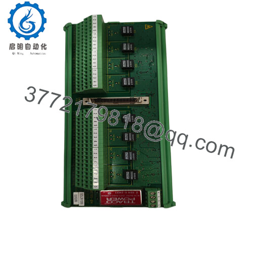
The ALSTOM MAE95-01 is a core processing and regulation board designed for legacy Cegelec Alspa and Synchrodrive variable speed drive systems. This card acts as the central coordinator for drive firing sequence calculations, monitoring feedback loops from high-power inverter circuits, and generating precise gating pulses to regulate motor speed and torque. Manufactured in France with premium industrial-grade components, its multilayer printed circuit board layout features high-density CMOS logic chips that deliver real-time loop response times necessary for heavy-duty applications like marine vessel propulsion, mine hoists, and metal rolling mills.
From a procurement perspective, keeping a verified New Surplus MAE95-01 on-site is a fundamental way to reduce operational risk. Since the Cegelec/Alstom Synchrodrive platforms are no longer supported by the OEM, finding replacement components during an unexpected outage can be extremely difficult. Used or refurbished options carry hidden risks like component aging from long-term exposure to heat inside drive cabinets, which can lead to unpredictable signal drift. Sourcing this pristine, zero-hour New Surplus module avoids those issues, guarantees standard factory reliability, lowers your Total Cost of Ownership (TCO), and protects your plant from expensive, unscheduled production halts.

- MAE95-01
5. Installation & Configuration Guide
Stage 1: Pre-Installation (Prep & Safety)
- Turn off the main feeder breaker to the drive enclosure. Follow standard lock-out/tag-out (LOTO) safety protocols for both the high-voltage input lines and low-voltage auxiliary control circuits.
- Wait a minimum of 30 minutes to let the primary intermediate DC bus capacitors discharge completely. Test the circuit with a calibrated digital multimeter to confirm that the voltage is well below safe thresholds (under 50 V DC).
- Put on a grounded electrostatic discharge (ESD) wrist strap and connect it to a bare metal grounding point on the enclosure frame.
- Take detailed photos of the original card’s layout, noting the positions of any configuration jumpers, DIP switch arrays, or ribbon cable routes.
Stage 2: Removal
- Unplug any auxiliary flat-ribbon data cables or front-panel feedback wires connected to the card.
- Release the plastic ejector clips or mounting screws holding the board firmly within the chassis card rack.
- Slide the card out of its slot rails by pulling evenly on both corners. Avoid twisting the board, which can scratch the copper traces or damage the delicate backplane connector pins.
Stage 3: Installation (Clone & Seat)
- Unbox the New Surplus ALSTOM MAE95-01 card within an ESD-safe workspace.
- Match all jumper blocks and DIP switch configuration switches on the new board to look exactly like the unit you just removed.
- Align the edges of the PCB with the plastic track guides inside the card cage. Push the module into the slot until it seats securely into the backplane receptacle.
- Reconnect all front-facing data harnesses and ribbon cables, double-checking that orientation markers line up perfectly.
Stage 4: Power-On & Testing
- Re-energize the low-voltage auxiliary logic power supply to the drive rack.
- Check the card’s LED status indicators. The system should initialize cleanly with a solid green status light and no active fault signals.
- Run a low-speed drive test configuration to make sure the gate-firing loops and speed feedback calculations are working correctly before ramping up to full production loads.
6. Firmware/Software Versions & Upgrade Notes
The ALSTOM MAE95-01 operates using a combination of analog monitoring loops and digital logic controllers configured via physical component layouts and on-board programmable microchips. This hardware does not feature field-updateable flash memory ports.
Because system response profiles are hardcoded to the specific product revision level (such as MAE95-01 versus later MAE95-02 revisions), you must replace broken cards with the exact same model designation. Swapping this component with a different model revision without verifying system compatibility can lead to phase-angle mismatches, timing drops, or synchronization faults within the drive inverter section.
7. Frequently Asked Questions (FAQ)
- Why choose a New Surplus MAE95-01 board over a cheaper refurbished option?
Refurbished drive boards have usually run for years inside hot industrial control cabinets, which slowly degrades internal components like capacitors and optocouplers. This New Surplus card has never been put into service, meaning all of its tracking circuits are pristine and perform exactly to original OEM specifications, keeping your system safe from unexpected early breakdowns.
- Is this card compatible with modern Alstom or GE drive platforms?
No. The MAE95-01 is built exclusively for legacy Cegelec Controls Alspa and Synchrodrive variable speed systems. It cannot be used in modern AC or DC drive platforms that rely on completely different digital communication styles and fiber-optic gate control setups.
- Does this processing card come pre-configured from the factory?
The board includes standard factory logic circuits and basic operating microcode. However, you must manually copy and configure any physical jumper setups and DIP switches from your existing card to ensure it matches your site’s specific motor and feedback requirements.
- What is the primary cause of damage to these control boards?
The two most common causes of card failure are overheating from clogged cabinet cooling filters and electrostatic discharge (ESD) during maintenance. Always maintain clean ventilation across the card rack and wear a grounded wrist strap whenever handling the board.
- Can this card be pulled or replaced while the drive logic is energized?
No. Attempting to pull or insert the board while power is applied can create arc flashes across the backplane edge connector. This can ruin the board’s CMOS logic and permanently damage neighboring cards in the rack. Always power down the system completely before doing any maintenance.
- What type of warranty coverage do you provide with this module?
We include a comprehensive 1-year replacement warranty with this New Surplus board. This coverage protects your procurement investment and guarantees that the card will slide into your legacy system and operate reliably from day one.



