
 WhatsApp: +86 16626708626
 Email:
  Phone: +86 16626708626
Description
3. Key Technical Specifications
| Parameter | Value |
|---|---|
| Manufacturer | ALSTOM |
| Model Number | MT96-PAC000072 |
| Product Type | Industrial Control Module |
| System Designation | UMC 110VIE / EBM10 / NVR / IOC |
| Function | Control processing and system interface module |
| Application | ALSTOM legacy industrial automation systems |
| Mounting Type | Control cabinet / rack installation |
| Processor Configuration | Verify OEM documentation before installation |
| Communication Interface | Verify installed UMC system configuration |
| Power Supply | Verify from module label and rack documentation |
| Firmware | Record existing firmware revision before replacement |
| Condition Available | New Original (New Surplus) or Refurbished (tested) |
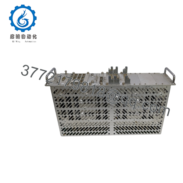
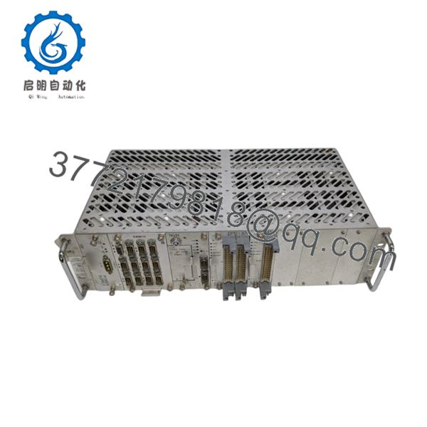
ALSTOM MT96-PAC000072 is listed as a UMC 110VIE/EBM10/NVR/IOC industrial control module. Exact electrical specifications and application role depend on the installed ALSTOM UMC system configuration.

- MT96-PAC000072
- MT96-PAC000072
4. Product Introduction
ALSTOM MT96-PAC000072 is an industrial control module used in ALSTOM UMC-based automation systems. The module is identified with the UMC 110VIE/EBM10/NVR/IOC configuration and is supplied for maintenance replacement of installed legacy control equipment.
For field replacement, verify the complete part number, rack location, firmware revision, wiring arrangement, and existing configuration records. Legacy ALSTOM modules can appear identical while requiring different software or hardware revisions.
5. Installation & Configuration Guide
Stage 1: Pre-Installation Preparation (Estimated Time: 5–10 minutes)
⚠️ Safety First:
- Notify operations before removing the MT96-PAC000072 module.
- Confirm the controlled equipment is in a safe maintenance state.
- Apply lockout/tagout procedures.
- Remove power and wait at least 5 minutes for capacitor discharge.
Tools Required:
- ESD strap
- PH1 screwdriver
- Fluke 115 multimeter
- Wire labels
- Smartphone for photos
Data Backup:
- Export available PLC/control configuration files.
- Record rack slot and module position.
- Photograph all connectors and terminal wiring.
- Record module serial number and hardware revision.
- Document communication settings and firmware version.
Stage 2: Removing the Old Module (Estimated Time: 5 minutes)
- Remove cabinet cover or protective panel.
- Label all wiring before disconnecting.
- Disconnect connectors carefully.
- Release rack locking tabs or retaining hardware.
- Pull the module straight out.
- Inspect the backplane connector for dust, bent pins, or damage.
⚠️ Note: Keep the original MT96-PAC000072 until the replacement completes commissioning. The old unit is the best reference for revision comparison.
Stage 3: Installing the New Module (Estimated Time: 10 minutes)
- ESD Preparation: Wear a grounded wrist strap before handling the module.
- Verify:
- ALSTOM marking
- MT96-PAC000072 part number
- Hardware revision
- Configuration Clone (Critical):
- Match rack position.
- Copy jumper/DIP switch settings if present.
- Confirm communication configuration.
- Insert the module into the rack.
- Confirm the module is fully seated.
- Reconnect wiring using correct terminal handling practice.
Self-Checklist:
- Part number verified
- Hardware revision matched
- Configuration copied
- Wiring secured
- Rack locking tabs engaged
Stage 4: Power-On & Testing (Estimated Time: 10–20 minutes)
Pre-Power Check:
- Verify supply voltage with a Fluke 115 multimeter.
- Confirm no short condition exists on the power rail.
Power-On Steps:
- Power the control rack only.
- Check module LED/status indicators.
- Connect engineering software if applicable.
- Verify module recognition.
- Confirm communication status.
- Restore saved configuration if required.
- Perform controlled system testing.
⚠️ Troubleshooting Note:
If the module fails to communicate, check firmware mismatch, rack addressing, power supply capacity, and configuration files first.
6. Frequently Asked Questions (FAQ)
Q: Can I hot-swap the ALSTOM MT96-PAC000072 module?
A: No, do not assume this module supports hot replacement. Remove power before extraction unless the exact UMC system documentation confirms otherwise. Live removal can damage the backplane or cause controller faults.
Q: Is the ALSTOM MT96-PAC000072 obsolete?
A: This is a legacy ALSTOM control module, so availability depends on remaining inventory, surplus stock, and tested refurbished units. Verify compatibility before ordering because UMC configurations can vary.
Q: Is the MT96-PAC000072 genuinely new?
A: Confirm the condition before purchase. New Original / New Surplus units should retain original markings and unused condition. Refurbished units should include inspection and functional test records.
Q: Will I lose my PLC program when replacing this module?
A: Do not assume the module contains or does not contain application data. Save all available configurations before removal. The safest replacement process starts with a complete backup and documentation of the running system.
Q: What is the direct replacement for MT96-PAC000072?
A: A direct replacement depends on the installed UMC architecture, firmware, rack configuration, and application. Match the complete part number and system documentation before selecting an alternative.
Q: What is the most common mistake during MT96-PAC000072 replacement?
A: Engineers often focus only on the part number. I have seen legacy control replacements delayed because the module matched physically but the firmware revision or configuration did not match the running system.
Q: What inspection process should be completed before shipping an MT96-PAC000072?
A proper industrial QC process should include:
- Inbound Inspection & Traceability
- Verify source documentation.
- Confirm serial number and manufacturer markings.
- Inspect for corrosion, scratches, rework marks, and physical damage.
- Audit manuals and included documentation.
- Live Functional Testing
- Test on a compatible ALSTOM UMC rack or simulation system.
- Verify power-up sequence.
- Check LED/status behavior.
- Perform communication handshake tests where applicable.
- Run continuous operation testing for more than 24 hours.
- Generate an official test report.
- Electrical Parameter Testing
- Insulation resistance test using a 500 V Megger where applicable.
- Ground continuity verification.
- Additional electrical checks based on module design.
- Firmware & Configuration Verification
- Record firmware version.
- Document hardware revision.
- Photograph configuration settings.
- Final QC & Packaging
- QC inspector sign-off.
- Anti-static ESD bagging.
- Bubble wrap and heavy-duty corrugated boxing.
- QC Passed label with inspection date.
Test photos and videos should be available upon request. Verified functional testing under controlled conditions is the correct standard for legacy ALSTOM automation modules.



