WhatsApp: +86 16626708626
 Email:
 Phone: +86 16626708626
Description
Key Technical Specifications
| Parameter | Specification |
|---|---|
| Manufacturer | ALSTOM |
| Order part number | NRD108031 |
| Board identification | TRVC070999000 |
| Board position marking | BOTTOM |
| Product type | Control circuit board / board assembly |
| Reported system association | GEM80 legacy control system |
| Board arrangement | Reportedly the lower board in a dual-board assembly |
| Bus architecture | VME bus is claimed by one supplier; verify against the original hardware documentation |
| Processor and memory details | Not independently verified |
| Rated voltage and current | Not verified |
| I/O channel count | Not verified |
| Connector pinout | Not verified |
| Dimensions and weight | Not verified |
| Operating temperature | Not verified |
| Lifecycle status | Current manufacturer status not confirmed |
Technical accuracy note: Supplier listings disagree on the board’s functional classification, with descriptions ranging from a VME processor base board to a digital-input or general control board. These descriptions are insufficient to establish a definitive specification. Do not use unverified voltage, pinout, memory, or I/O data for installation or engineering approval.
Product Introduction
The ALSTOM NRD108031 TRVC070999000 BOTTOM is a legacy circuit-board spare listed for maintenance of existing industrial control equipment. One supplier associates it with a GEM80 turbine-control assembly and describes it as the lower board in a dual-board configuration. Because the precise board function has not been confirmed by an authoritative technical manual, procurement should be based on the complete part marking, physical layout, connector arrangement, and installed-system documentation rather than the model number alone.
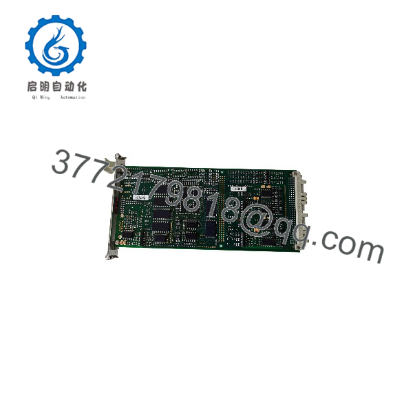
NRD108031 TRVC070999000
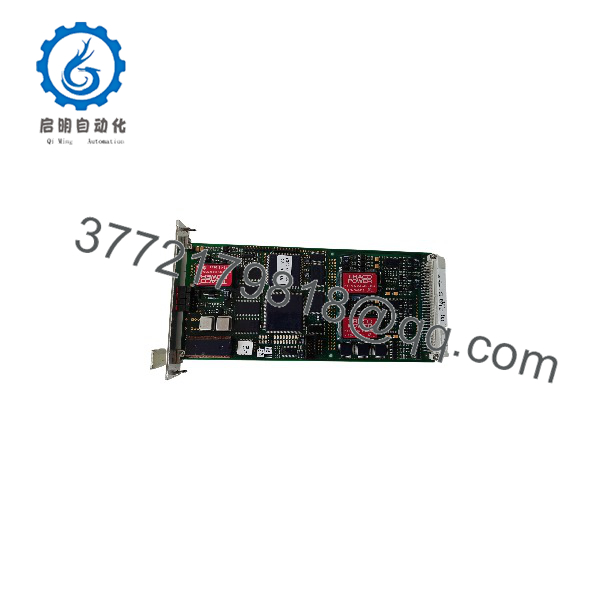
NRD108031 TRVC070999000
Installation & Configuration Guide
Confirm the exact board
- Check the nameplate and PCB silkscreen for
NRD108031andTRVC070999000. - Confirm that the board is marked
BOTTOM. - Photograph the front and rear of the existing board, including connectors, revision labels, and component identifiers.
- Identify the installed control-system model and the associated upper board.
Prepare the equipment
- Follow the plant’s approved shutdown and lockout/tagout procedure.
- Isolate the relevant power sources and verify the equipment is safe to service.
- Use appropriate electrostatic-discharge (ESD) protection when handling the circuit board.
- Record existing wiring, board orientation, slot position, and connector locations before removal.
Inspect and install
- Compare the replacement board’s PCB layout, connectors, mounting points, and revision markings with the original.
- Inspect connectors for corrosion, bent contacts, contamination, or mechanical damage.
- Install the board only in the documented slot and assembly configuration.
- Do not assume that a visually similar NRD-series board is electrically interchangeable.
Verify system compatibility
- Confirm the board’s role and interface requirements from the original equipment drawings or service manual.
- Verify the associated board, backplane, firmware, and configuration requirements.
- Do not connect power or field wiring based solely on third-party product descriptions.
Commission the equipment
- Follow the OEM’s approved restart procedure.
- Check system diagnostics and alarm status before enabling normal operation.
- Perform the prescribed functional tests and verify the relevant control signals.
- Document the replacement part number, revision, test results, and any configuration changes.
Safety note: If this board is installed in a turbine-control or protection system, replacement and testing should be carried out by qualified personnel using the applicable OEM procedure. Do not bypass protective interlocks or test safety functions without an approved test plan.
Frequently Asked Questions
Q1: What is the ALSTOM NRD108031 TRVC070999000 BOTTOM?
It is a legacy ALSTOM circuit-board spare. One supplier identifies it as a lower board in a GEM80 control-system assembly, but its exact functional role requires confirmation from the original technical documentation.
Q2: What does “BOTTOM” mean?
The supplier description interprets “BOTTOM” as the lower board in a dual-board assembly. Confirm the board position against the equipment drawings before installation.
Q3: Is it a processor board or a digital-input board?
Available supplier listings conflict. One describes a VME-bus processor bottom board, while another describes it as a digital-input module. Neither description alone is sufficient to establish its definitive function.
Q4: Can NRD108031 replace another NRD-series board?
Not without an engineering compatibility check. Similar part-number prefixes do not establish matching electrical characteristics, connector assignments, firmware requirements, or functional behavior.
Q5: Is the NRD108031 still manufactured?
I could not verify its current production status from an official ALSTOM source. Ask the supplier or equipment service provider to confirm whether the required revision is available as new, unused surplus, refurbished, or used equipment.
Q6: What should I request from a supplier before purchasing?
Request clear photographs of both PCB sides, the complete nameplate, revision information, connector details, a functional test report, and confirmation of compatibility with the installed system.
Q7: What information is needed to confirm the exact specifications?
The most useful evidence is an OEM parts list, board schematic, equipment wiring diagram, or service manual identifying and TRVC070999000. A photograph of the existing board can also help establish its physical configuration.