
 WhatsApp: +86 16626708626
 Email:
  Phone: +86 16626708626
Description
Key Technical Specifications
| Parameter | Value |
|---|---|
| Manufacturer | Alstom / Converteam |
| Model Number | PIB100G / PIB100 G |
| OEM Tracking Code | 3BEE0226 A / 123032604 |
| System Interface | VME Rack Bus compatible (BGTR 8HE 8-Slot frames) |
| Product Classification | Power Interface Board / Drive Controller Add-On Card |
| Logic Logic Power | 24 V DC nominal input supply |
| Local Visuals | Integrated 1-digit 7-segment LED diagnostic display |
| Network Interfaces | Controller Area Network (CAN Bus) link layers |
| Port Mapping | Dedicated transceiver (receiver/transmitter) and serial ports |
| Cooling Profile | Natural convection cooling inside VME enclosure space |
| Net Weight | 0.45 kg (1.0 lb) |
| Operating Temperature | 0 to +60 °C local operating envelope |
Product Introduction & Supply Chain Strategy
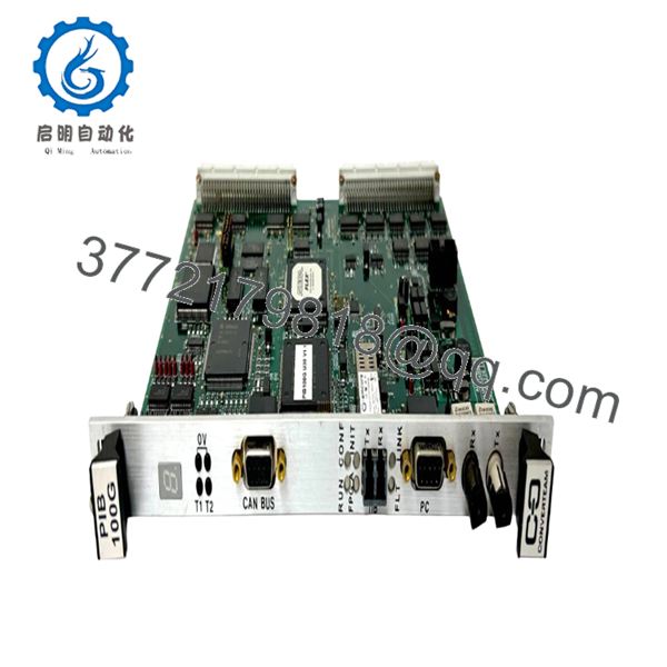
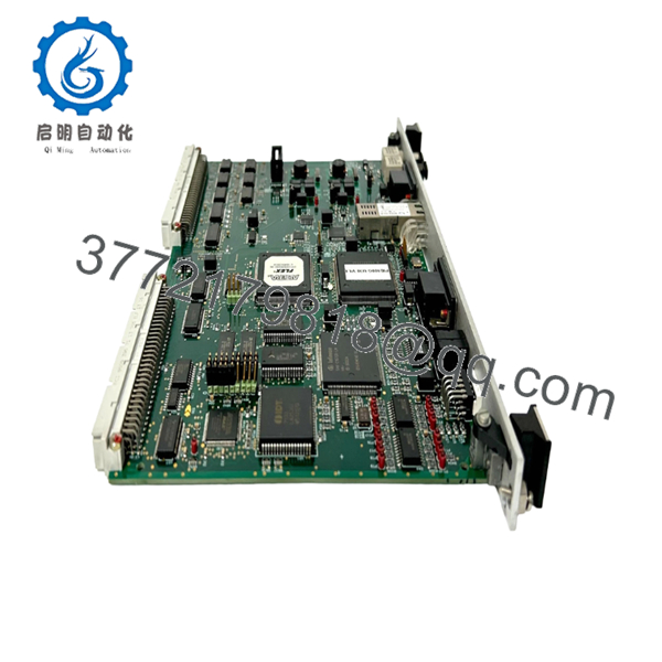
The Alstom PIB100G (3BEE0226 A) is a specialized, high-reliability Power Interface Board engineered for the Alspa power conversion and VME-based drive control platforms (such as the Converteam BGTR 8HE 8-slot rack system). Positioned as an essential communications and isolation bridge, this module bridges the high-level control circuits with the high-power inverter gates. It leverages an integrated CAN Bus network layer and synchronous transceiver ports to handle real-time signal routing, while an on-board 1-digit 7-segment LED display provides localized error codes and system status readouts.
Because the PIB100G series has transitioned to complete manufacturer obsolescence, it represents a single point of failure within older automated drive lines. Maintaining an untouched, New Surplus unit in your local warehouse serves as an essential safety stock policy to eliminate prolonged lead time variability during emergency turnarounds. Procuring this part as a genuine New Surplus module lowers your Total Cost of Ownership (TCO) compared to the downstream expenses of unpredicted system drops. It also eliminates the risks of component value drift, micro-fractured PCB traces, and latent capacitor aging commonly found in low-quality refurbished boards.

- PIB100G
- PIB100G
Installation & Configuration Guide
Stage 1: Pre-Installation (Prep & Safety)
- Initiate complete site lock-out/tag-out (LOTO) procedures on the target VME rack assembly and its master power distribution boards.
- Verify that the auxiliary 24 V DC power bus bar reads a true zero-voltage state with a calibrated digital multimeter.
- Secure an ESD-grounding wrist strap to your arm, connecting the reference line directly to an unpainted structural ground bracket.
- Record the original layout. Take detailed photos of any daughterboard links, DIP switches, and external serial/CAN connection terminations.
Stage 2: Removal
- Loosen the upper and lower faceplate extraction tabs and retaining screws securing the PIB100G board inside the rack.
- Gently detach any front-facing network lines or serial cables from their respective ports, noting their exact tracking destinations.
- Pull the module handles straight outward along the VME chassis slot tracks. Apply uniform horizontal force to avoid bending any backplane pin connections.
- Put the pulled card directly into an ESD-shielded antistatic container.
Stage 3: Installation (Clone & Seat)
- Open the new surplus PIB100G card inside a static-shielded clean zone.
- Align all physical board jumpers, jumpers, and DIP switches to match the exact topology of the module being replaced.
- Guide the board along the VME chassis guide rails, sliding it smoothly back until the rear edge pins seat completely into the VME backplane matrix.
- Fasten the faceplate captive screws to secure frame ground connectivity, and snap the serial and CAN Bus transceiver lines back into position.
Stage 4: Power-On & Testing
- Verify that the power rails are stable and within the 24 V DC nominal parameters.
- Apply logic power to the VME rack.
- Watch the front-panel 1-digit display during initialization: verify that the boot cycle progresses through its starting configurations without hanging on a persistent fault indicator.
- Access the master Alspa programming interface to verify active network loop handshakes and confirm real-time data flow across the power conversion bus.
Firmware/Software Versions & Upgrade Notes
The PIB100G operates on dedicated microcode structures that coordinate high-speed communication routing between the VME backplane bus and the CAN network layers. To maintain synchronization, this card must run matching firmware builds when integrated alongside companion boards (such as the PIB101C or PIB310 modules).
When installing a replacement PIB100G card, do not attempt to flash firmware revisions or modify local configuration code on an active control network during critical recovery windows. Mismatched communication timings will cause the system to drop network handshakes, causing the host controller to flag a bus fault and drop the drive offline. Always match the hardware revision code stamped on the incoming card (such as revision suffix 3BEE0226 A) against your facility’s system logbook before approving full loop operation.
Frequently Asked Questions (FAQ)
Q: What is the purpose of the 1-digit display on the front faceplate of the PIB100G? A: The integrated 1-digit 7-segment LED display is a real-time diagnostic interface. During system startup, it advances through numbers representing internal self-test phases. During operation, a steady, expected character confirms normal processing health, while specific alphanumeric codes pinpoint localized communication or power isolation failures without needing a separate laptop tool.
Q: Are Alstom, Converteam, and Cegelec versions of the PIB100G completely identical? A: Yes. Due to corporate restructuring and acquisitions, this module line has been branded under the Cegelec, Alstom, and Converteam names. As long as the base model number (PIB100G) and internal production code (3BEE0226) match, the boards are fully form-factor compatible and functionally interchangeable across all legacy drive platforms.
Q: Can this power interface board be hot-swapped while the VME rack is energized? A: No. The PIB100G card routes high-speed processing data across a shared VME backplane bus. Attempting to insert or extract this module while the slot is live can generate transient arcs across backplane pins, risking data corruption in adjacent processing nodes or causing an immediate control drop on the main power conversion line.
Q: Why choose New Surplus over a much cheaper used or repaired PIB100G module? A: Power interface boards encounter continuous thermal cycles and minor electrical stresses that over time degrade internal semiconductors and timing components. A refurbished or used module has already burned through a significant portion of its design life, leaving it vulnerable to sudden component failure. Our New Surplus stock provides an untouched, factory-clean configuration with its full lifetime margin intact, minimizing unexpected downtime and lowering your overall Total Cost of Ownership (TCO).
Q: What type of warranty protection is provided for this legacy Alstom board? A: Because the original equipment manufacturer long ago concluded factory production and lifecycle support for this series, factory warranties are unavailable. To ensure your facility’s operational safety, we back this genuine New Surplus PIB100G module with our own comprehensive 2-year warranty that protects against all mechanical component failures and functional electrical defects.



