
 WhatsApp: +86 16626708626
 Email:
  Phone: +86 16626708626
Description
Key Technical Specifications
| Parameter | Value |
|---|---|
| Manufacturer | Applied Materials (AMAT) |
| Part Number | 0100-71311 |
| Product Type | Semiconductor system card / power-port accessory |
| Primary Function | Power-rack alarm signal interface |
| Signal Function | Converts alarm signals to non-voltage alarm contacts |
| PCB Construction | Printed circuit board with connectors, relays, and alarm-contact circuitry |
| Installation Location | Rear of compatible power rack |
| Rack Connection | 25-way D-type female connector reported |
| Mechanical Retention | D-sub connector screws |
| Application | Semiconductor manufacturing equipment |
| Associated Equipment | Power box / power rack |
| Communication Protocol | No standard fieldbus protocol documented in the available sources |
| Input Voltage | Not reliably documented |
| Operating Temperature | Not reliably documented |
| Dimensions | Not reliably documented |
| Weight | Not reliably documented |
Technical verification note: Public reseller documentation provides a functional description but does not establish reliable values for supply voltage, contact ratings, temperature range, dimensions, or pin-by-pin electrical characteristics. Those values should not be inferred from generic industrial I/O specifications.
Product Introduction
The AMAT 0100-71311 is a semiconductor-equipment system card used as a power-port accessory on compatible Applied Materials power racks. Available documentation describes it as a PCB containing connectors, relays, and alarm-contact circuitry that converts alarm signals generated by the power box and power rack into non-voltage alarm contacts for the equipment control system.
The board is therefore an alarm-interface component rather than a conventional PLC analog or digital I/O module. The exact connector pinout, contact arrangement, supply requirements, and compatible equipment platform should be confirmed against the installed AMAT configuration before replacement.
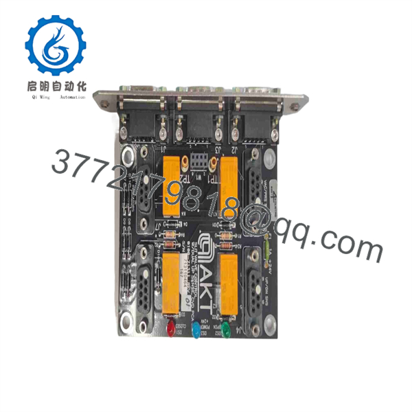
0100-71311
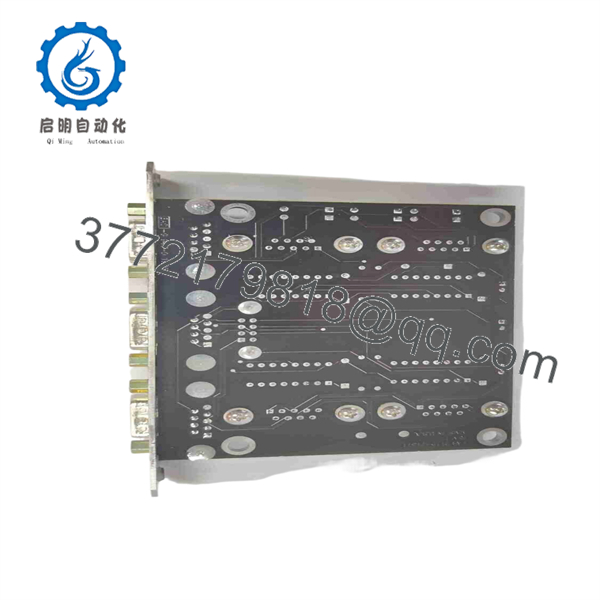
0100-71311
Installation & Configuration Guide
Stage 1: Pre-Installation Preparation — Approximately 10 Minutes
⚠️ Safety First: Place the Applied Materials tool into its approved service condition. Follow the equipment-specific shutdown sequence and lockout/tagout (LOTO) all applicable energy sources before accessing the power rack.
Tools Required:
- ESD wrist strap
- Digital multimeter
- Appropriate Phillips/flat-head screwdriver
- Connector labels
- Smartphone or camera
- OEM equipment service documentation
Data Backup:
- Record the equipment model and power-rack configuration.
- Photograph the existing 0100-71311 from both sides where accessible.
- Record all visible PCB markings and revision information.
- Photograph the complete connector arrangement.
- Label every cable before removal.
- Record the alarm wiring associated with the power rack.
- Preserve the existing board until the replacement has passed functional testing.
⚠️ Do not assume that a visually similar AMAT PCB has the same alarm-contact pinout.
Stage 2: Removing the Old Module — Approximately 5 Minutes
- Confirm that the equipment is in the approved maintenance state.
- Establish ESD protection before handling the PCB.
- Open the power-rack access area according to the equipment service procedure.
- Photograph the connector and cable orientation.
- Label all connections before disconnecting them.
- Disconnect the board from the reported 25-way D-type interface where applicable.
- Remove the board’s mechanical retaining hardware.
- Carefully remove the PCB without stressing the connector.
- Inspect the mating connector for bent pins, contamination, oxidation, or mechanical damage.
- Keep the original board available for direct comparison.
Stage 3: Installing the New Module — Approximately 5 Minutes
- Verify the replacement marking: AMAT 0100-71311.
- Compare the replacement PCB with the removed assembly.
- Confirm connector position and mechanical mounting points.
- Use grounded ESD protection while handling the board.
- Position the PCB correctly on the power-rack mounting interface.
- Install the retaining hardware without excessive torque.
- Connect the D-type interface.
- Verify that the connector is fully seated and mechanically secured.
- Recheck every alarm connection against the photographs and OEM wiring documentation.
- Inspect the assembly for loose hardware or trapped wiring.
Self-Checklist:
- Part number matches
- Board configuration matches
- Connector orientation verified
- Alarm wiring labeled
- D-type connector fully seated
- Retaining screws secured
- No loose hardware
- ESD precautions maintained
Stage 4: Power-On & Testing — Approximately 10 Minutes
- Perform a final visual inspection.
- Verify that no tools or foreign objects remain inside the rack.
- Restore power according to the OEM startup procedure.
- Check the board and equipment diagnostic indications.
- Verify that the power rack reports its expected operating state.
- Exercise the applicable alarm conditions using the approved maintenance/test procedure.
- Confirm that the corresponding alarm contacts are correctly recognized by the system.
- Check the equipment event or alarm log.
- Verify that no new power-rack or alarm-interface faults are present.
- Return the equipment to production only after the required interlock and alarm tests pass.
⚠️ Troubleshooting Note: If the equipment does not recognize an expected alarm, check the connector seating, wiring, contact configuration, power-rack interface, and equipment-specific pinout before condemning the PCB.
Frequently Asked Questions (FAQ)
Can the AMAT 0100-71311 be hot-swapped?
Do not assume that it can. The available documentation identifies the board as a power-rack accessory but does not document a hot-swap capability. Perform the replacement with the equipment in its approved maintenance state and follow the applicable AMAT service procedure.
What does the 0100-71311 actually do?
Its documented function is to interface alarm signals generated by the power box and power rack and convert them into non-voltage alarm contacts for the system. The board contains connectors, relays, and associated alarm-contact circuitry.
Is 0100-71311 a conventional PLC digital I/O module?
Not based on the strongest available part-specific description. Although some resellers categorize it generically as an industrial input/output module, more specific listings describe it as a power-port accessory / semiconductor system card for a power rack.
What connector does the 0100-71311 use?
One detailed listing reports that the compatible power supply rack has a 25-way D-type female connector and that the power port connects through this interface. Verify the actual connector and pin assignment on the equipment before installation.
Does 0100-71311 communicate over Modbus or Profibus?
No standard Modbus, Profibus, or EtherNet/IP interface is documented in the sources reviewed for this exact part number. Its described function is electrical alarm-contact interfacing rather than network communication.
Is the 0100-71311 obsolete?
The sources reviewed do not provide authoritative Applied Materials lifecycle documentation establishing an official obsolete or active-production status. It is currently listed by industrial spare-parts suppliers, including listings describing both new and used availability.
What should I verify before purchasing a replacement?
Give the supplier the complete 0100-71311 part number, equipment/tool model, board photographs, visible revision markings, and connector configuration. For this type of semiconductor-equipment spare, matching the material number alone is not sufficient if the installed assembly has a different revision or equipment-specific wiring configuration.



